
The track used to build this layout is all readily available manufactured flex track and switches laid on 1/4" cork roadbed, this is the same method used since my first 4 x 8 HO layout built in 1957 and one that I am familiar with. Although this layout does not have a particularly large dimensional foot print, with the many levels and abundant staging there was a lot of track to be installed, therefore in the interest of construction time once again the use of manufactured track and switches fit my comfort level.
Track centerlines were determined during the planning stage, then transferred to and drawn onto the bare plywood benchwork/sub roadbed to accurately guide the placement of the roadbed and the following track.
Minimum radius of track curvature on this layout is 26", this only occurs in the dual track helix. Easements are integrated between tangent and curved track. Maximum grade is 2.25%, this is also only within the helixes.
Layout is powered by a Digitrax DCC system with radio throttles. Power is applied to the rails via a 12 gauge buss wire and 22 gauge wire feeds to each piece of flex track. There are five separate power zones each protected by a circuit breaker.
Roadbed
The roadbed is all 1/4" cork affixed to 3/4" plywood. Single track applications are standard commercially available 3' lengths of cork, I like the natural color cork from Model Railway Post Office. Areas with multiple parallel track or yards the roadbed was cut to size from 1/4" cork floor underlayment purchased in a 4' wide roll from Home Depot.
All cork was affixed to the plywood with latex adhesive caulk with silicone. Using this caulk is a departure from the Elmer's white glue that I have used in the past. The caulk remains supple after curing and seems to transfer less noise from the rolling stock than my prior layouts where hard when cured Elmer's glue was used to affix the cork. All cork roadbed in visible areas of the layout was painted flat black after installation using interior latex wall paint.
For single track roadbed a thin bead of caulk was dispensed on either side of the track center line and spread evenly with a 1 1/2" plastic putty knife. For double track or yard roadbed the caulk was dispensed then spread evenly with a notched trowel as seen in the photos below. After the cork was in place a wallpaper roller was used to work out any air pockets that may be trapped between the cork and the plywood therefore leaving a smooth surface to affix the track to. After the cork roadbed is painted flat black and thoroughly dried, a sanding block with 80 grit sandpaper is used to eliminate any irregularities in the roadbed before track laying.


Track
Two brands of flex track were used on the layout.
Atlas code 83 was used in staging and other areas of the layout where the track is not part of the finished scene. This track was chosen for its easy to bend qualities and speed of installation. This track will not hold its shape after bending and requires mechanical assistance to hold its shape while affixing to the roadbed, push pins and weights were used for this.
Micro Engineering code 70 weathered track is used in all areas of the layout that will have a finished scene. This track was chosen for its lower profile and more realistic appearance. This track is much harder to bend but once bent will usually hold its shape without any mechanical assistance.
Laying Track
All track is affixed to the roadbed using the same adhesive caulk that was used to affix the cork roadbed to the plywood. Again I think the flexible nature of this caulk when it has cured helps noise reduction in the finished product.
Single track is laid using the centerline where the two halves of the commercial cork roadbed are joined as a guide. Tangent parallel and Yard track was laid to centerlines drawn on the painted roadbed with a white pencil.
Below is one of the last pieces of track to be laid in the Danbury yard. Because this track has compound curves, I find it easier to first use a piece of the very flexible Atlas track (not shown) as a tool to mock the final positioning of the track to be laid then pin it down and mark the outside of the ties with a white pencil then use those two lines to locate the Micro Engineering track instead of working from a centerline.


I find that the Micro Engineering track is very hard to bend in comparison to the Atlas track. I do not know if this is unique to the weathered track or not because only weathered track was used. The best tool I could find to form the bends in this track is a metal Kadee coupler height gauge like the one below.


Run the Kadee gauge back and forth over the track to force the track inward where it needs to be bent as below. Initially the ties will go askew but rubbing the edge of the gauge seen above back and forth over the backside of the ties will put them back in place


Continue running the gauge back and forth until the bend is finalized.

Gluing Down Track And Ballast
Adhesive caulk is used to affix the track, again I used the caulk because it remains flexible after curing and I find that it helps reducing noise transfer from the rolling stock. Below two thin beads of caulk have been dispensed where track will be placed.

This photo shows the brand and type of caulk that has been used for this entire layout. This caulk cures clear in color as noted on the top of the tube.

Caulk is spread with a putty knife and worked to a thin and even coating where track will be placed.

After track is in place, applying pressure while rolling a piece of rolling stock back and forth over the track will settle the track into the caulk, this is usually enough for the Micro Engineering track to hold its shape without any mechanical help.

Painting Track And Ballast
After the track is in place and the caulk has cured the track is painted with a flat color to hide the shine of the plastic ties, I like a color named "rail tie brown" for this initial coat. This coat of paint is a uniform base color that additional colors of paint washes or pastels will be applied later in the scenery phase. Below an air brush is used to apply the paint.

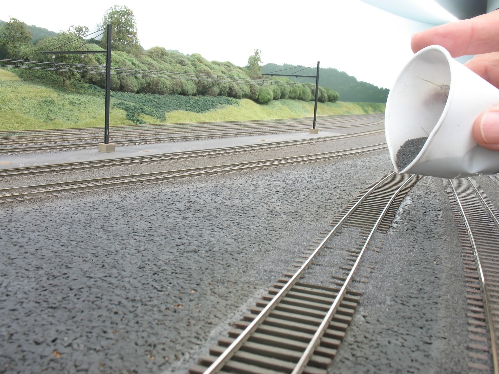
Ballast on the layout is from Scenic Express. I like their #40 Dark Gray Limestone, this is a natural stone aggregate that has weight to it and will not float around when using a wetting agent or Appling the fixative. Below the ballast is dispensed from a plastic bathroom cup then rubbed in place between the ties with a finger.

Isopropyl rubbing alcohol (70%) is used as a wetting agent, here it is being dispensed from a pipette.

Matte medium is used as a fixative. Again I do not think matte medium dries as rock hard as white glue and therefore will offer a quieter roadbed. I mix one part of matte medium with three parts of distilled water and again dispense it with a pipette.

Switches
Micro Engineering # 6 switches are used in all the scenic areas of the layout. I have had very reliable service from these switches on this layout and my last and never had to replace one. These switches are called "DCC friendly" by the manufacturer and have an electrically isolated frog. The frogs on this layout receive power thru the Tortoise switch machines that power them.
As manufactured the point rails receive their power from where they meet with the closure rails via a rail joiner hinge or contact with the stock rail or diverging rail. To assure absolute reliable power to the point rails I have added a light gauge wire between the point rails and the closure rails.

Thin 32 gauge stranded wire was used to make the connection between the point rails and the closure rails. The wire was soldered on the point rails as close to the hinge as possible where the throw radius is the slightest, this and the use of stranded wire do not foul the movement of the rails. A ball end mill in a Dremel tool was used to make a valley in the ties so the wire would lay flush with the bottom of the ties.

To ballast around the throw bar so its movement would not be obstructed by the ballast or its fixative, a dam made of strip caulk was applied surrounding the throw bar. This caulk will make a liquid proof dam that will prevent any liquid fixative from fouling the throw bar or dripping down to a lower level or the floor. I also use this caulk to plug up holes where electrical feeder wires are attached to the rails for the same reason. 3M Strip-calk was used for this, it is available at automotive supply stores. This caulk is very sticky and remains pliable.
I have found many other uses for this strip caulk on a model railroad. I use this for installing light bulbs (now LED's) in the shells of locomotives and lately am now using this to mount sound decoder speakers. I find that mounting speakers with this soft caulk absorbs any vibrations from the speaker housing therefore not transferring any harmonic to the loco chassis or rails.

Below a piece of the strip caulk is being placed around the ties that surround the throw bar. It is tamped down tightly against the cork roadbed and the ties with the back end of a skewer stick.

Below is the completed caulk dam.

Ballast is then added to the caulk, no fixative is needed, the ballast will permanently stick after it has been pressed into the caulk.


Rail Joints
Taking a cue from the prototype I like to stagger the rail joints if possible. I find in doing this the rails are less likely to kink at the joints, this is specially useful in curves like the Atlas staging track and finished Micro Engineering track below.


Joe, that mention of strip caulk is awesome, I never knew such a thing existed! Since I use pink insulation foam as my layout base (no Homasote or plywood) and no subroadbed (and no cork), I have some big holes where the upward throws for my Blue Points come up. I experienced a place where the ballast (sanded grout in my case) just rained down on the floor (and everything else underneath on the way to it), so I stopped. This stuff may be the trick I need to keep that from happening again, so thanks!
ReplyDeleteRalph Heiss
S. Plainfield, NJ
Ralph, Give it a try, could very well cure your problem. I have found many uses for this Strip-Calk in model railroading. A little dab of it on the end of a screwdriver is great for holding those tiny little model railroad screws for one.
ReplyDeleteRegards, Joe
This comment has been removed by the author.
ReplyDeleteHey Joe - Can't believe I missed this one the first time around, so am glad you mentioned it on the ProtLayouts group. GREAT idea about the KD gauge - I only wish I'd know that before laying all my ME track - but I'll know for next time. And your ballast looks amazing! I think I'm going to have to get myself some Scenic Express #40 Dark Gray Limestone! Thanks again for posting all this great tracklaying content together in one place here.
ReplyDelete