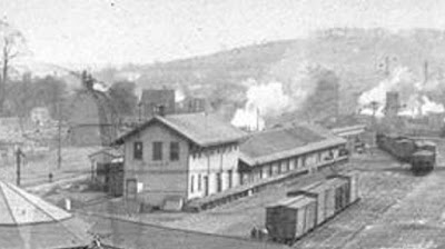
The three photos found most useful are below. The first is a cropped version of a early 1900's photo shown in part one, this shows the number of freight doors and their spacing.
Click to enlarge photos.
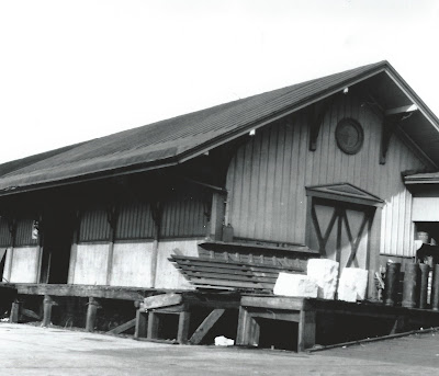
The next photo shows the types of siding used, freight door design, the spacing between the vertical support posts of the long side, the building end with window and the eve support brackets on both sides. The loading dock detail will be useful when modeling that.
The freight door, siding and eve support differences highlighted by that photo are represented in that same segment of the completed model below.
Modeling The Sides
The long sides of the single story model are about 30 actual inches in length. There are over 100 individual pieces to be cut and fitted then mated/glued together. Because of the large number of pieces to be joined and the length of the sides, all these joints would need reinforcement from behind for strength and linear stability.
To achieve the reinforcement necessary the sides were built in two layers. The first layer being a plain one piece reinforcement layer cut to the overall height and length dimensions of the side. The second layer being the visible layer with the multiple pieces glued over the first layer, the one piece first layer reinforcing all the joints of the second layer simultaneously. Both layers are .040 styrene.
The below photos show the numerous board and batten, V groove, door jamb and vertical support second layer pieces being test fit over the one piece first layer.
Normally these sides would have been built on a glass work surface but they are to long for the one on hand so a piece of tempered Masonite was subsututed.
Below the darker brown color has been applied and the remaining pieces now painted the lighter cream color are being glued and slid into place.
The completed side.
With all the second layer pieces painted and securely glued in place, the openings in the first layer for the freight doors can now be cut out.
Below one of the freight doors is being assembled. The styles, rails and center mullion have already been glued to the V groove door panel, cross bracing is being glued in place to complete the door.
When there are angles needing to be cut that are not of the usual 30° - 45° - 60° - 90° as with the angled cuts for cross bracing above, a temporary fence cut to the angle degree required is made for The Chopper. In the below photo one of those plastic cards received in junk mail works very well for this application.
A few passes with a file smooth all the pieces glued onto the door panel to the same plain.
Just before painting and in lieu of getting out the bondo, rubbing a soft eraser of a #2 pencil over the joints of the glued on door detail pieces fills in the gaps (fitting mistakes) between these pieces quite well.
To give the freight doors the ability to slide open and closed, door guides were made for the top and bottom of the doors. Below the top guides are being glued to the top inside of the of the buildings exterior side pieces.
After the building sides were glued to the foundation and floor, the bottom door guides were glued the building floor. To give the doors the ability to slide freely a small clearance gap between the all the guides and the back of the doors is necessary. In need of something to create these clearance gaps and would not be effected by the Tenax solvent glue used to attach the guides, a slick .012" business card from Pierre Oliver that came with the purchase of some detail parts at a RPM meet served that purpose well. Thank you Pierre.
Supporting The Roof
With the opening freight doors exposing the interior freight handling area, this area of the model was made to be completely open from obstructions from side to side and end to end. A ceiling was put in place over this long open span to affix the bulkheads necessary to adequately support the roof.
While browsing a hobby shop several years ago I came across these eve support brackets below made by Alexander Scale Models. Still at their original $1 for 12 pieces price they were a real find. These brackets are very close in detail to those of the prototype.
Note in the background of the photo below that a stone façade has been applied to the foundation simulating the prototype , looking at the photo above one can see what a waste of time this was after the loading dock will be permanently in place!
Some of the eve brackets on the end of the building.
This post is way to long, so next post will finish up with the the freight dock, the free standing concrete topped auto unloading dock, and some photos of the finished freight house at home on the layout.


Beautiful work - thanks for sharing research and construction details!
ReplyDeleteThank you Fred, This is a wonderful hobby, being able to share ideas, research and methods is one of the great traits of it.
ReplyDeleteJoe