
An original New Haven Railroad diagram of the EP-3 below was reproduced within the EP-3 article in the Shoreliner magazine Volume 34 issue 2 mentioned previously. This diagram provides all the basic overall dimensions necessary to build a model of the EP-3. Printing this diagram in HO scale will also provide dimensional data necessary for items not specifically sized on the diagram and their locations like windows, louvers, piping, tanks, handrails etc.
Click To Enlarge Photos

Reviewing the power chassis/frame dimensional data of the EP-3 above to that of a PRR GG1 reveals that the overall length of the GG1 is 2' 6" longer than the EP-3. The discrepancy is the distance between the driving trucks and the pony trucks whereas the distance is greater on the GG1. All other running gear dimensions appear identical.
The Power Chassis/Frame and "Porches"
Using the longer GG1 power chassis/frame with its dimensional discrepancy's described above as the foundation to build a model of the EP-3, some component length compromises will need to be made with the EP-3 prototype dimensions to compensate for the difference in length.
On the model, a decision was made to make the EP-3 box cab car body 2' 6' longer to compensate for the overall length discrepancy of the donor Bachmann GG1 power chassis/frame. The reason the car body was chosen is that the pantographs from the Bachmann GG1 will be reused on EP-3. These model pantographs are over-sized, so the extra length of the new car body will help them better fit onto the roof of the EP-3 among the other equipment needing to be located there.
The length of the streamline GG1 car body is near to the overall length of that locomotive, it covers the entire length of the power chassis/frame except the pilot faces and couplers.
The box cab EP-3 car body is significantly shorter than the overall length of the locomotive, this car body only encloses the mechanical and electrical components of the locomotive plus an operators station on both ends. The exposed deck area on both of the locomotive ends between the box cab and the pilot are referred to as "porches", see photo below.

The Bachmann GG1 power chassis/frame is made to fit tightly under the full length of that models car body.
To start the model of the EP-3, both ends of the Bachmann GG1 frame below were shortened 1.300" to fit under the new shorter box cab car body of the EP-3 and make room for the porches.

Below is one of the two plastic truck frames per locomotive that each drive and pony truck pair mount to, this assembly then swivels by and mounts to the cast metal power chassis/frame by the pivot shown. The pony truck mounts underneath the plastic truck frame with a screw. The GG1 pilot face details have been filed flat in preparation for the new porch components that will be affixed over the plastic truck frame. The GG1 step detail has been retained but squared up to match the style of the EP-3, later one additional step will be added above the bottom step.

The next photo shows a completed basic "porch", this will be glued over the plastic frame shown above. The pieces surrounding the completed porch are the component pieces that make up one porch. All parts are styrene.

The photo below shows a porch assembly permanently affixed to a truck frame. A buffer has been installed and the coupler release bar from the Bachmann GG1 will be reused. The lower pilot assembly is shown here but not permanently attached, this particular assembly has 15 separate parts and 32 drilled holes.

Below two truck/porch assemblies have been mounted under the power chassis/frame for a test fit.

The Box Cab Car Body
Car Body Sides
Both car sides and the cab ceiling between are glued together and mounted on the power chassis/frame in the below photo, all parts are made from styrene.
The cab ceiling and sides are .040" thick. The four side louvers are simulated with clapboard siding. The area designated in red in the photo from the horizontal belt line up is made with a double layer of .020 styrene, the inner layer outlines the stiles and rails of the windows. The horizontal belt line will be added after the cab ends are in place with .010"x.060" strip styrene.

Car Body Ends
The ends of the car body are semi-rounded, the center door is flat. The car body roof is fully rounded at the ends. A second original New Haven drawing from the Shoreliner EP-3 article below provided the correct radius to fabricate these pieces.

The photo below shows the cab end components on the left and a completed cab end on the right. The center ceiling piece is semi-round on both ends and will be located and glued to the top of the cab end inner-structure. The cab end sheets are made from thinner .020" styrene to help them conform to the cab end radius when gluing.

The following photos show the sides, ends and cab ceiling now all glued together and mounted on the frame.
A clerestory roof section from a Branchline coach kit was found to have the same arch radius as the EP-3 roof. The clerestory section was removed from the coach roof, it was cut to length of the ceiling piece and the ends trimmed to the correct radius. Matching the centerlines of the ceiling with the clerestory the two pieces were glued together. This will support the integrity of the roof curvature once the new roof is in place.

This photo shows the cab end crown piece in place, this piece matches the curvature of both the cab end and the arch of the roof. This is made from .010" stock for ease of gluing it to the curved cab end.

Car Body Roof
Pictures of the prototype EP-3 roof are rare but necessary for modeling. There is one good photo of the roof in the Shoreliner EP-3 article, modeling the roof details are mostly derived from that photo.
No photos were taken of just the basic roof piece. The roof was made from one piece of .010" styrene to best represent in scale the thickness of the prototype roof and for the ease of making the bends where the prototype roof panel contacts the car body sides for riveting. The roof ends were rounded, again using the overhead drawing as a guide for the correct radius.
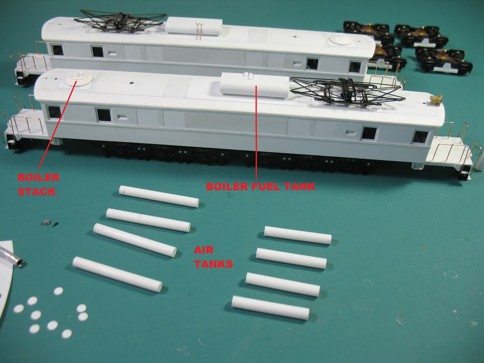
In photo below the roof has been glued to the car body. Boiler stack and large center tank have been mounted, trial fit for the pantographs and head light.
The assumption is that the large tank mounted on the center of the roof is the fuel tank for the boiler. The prototype tank has a 460 gallon capacity, so this would be about the right size for that, it was modeled as best possible from photos. If anyone knows differently please make a correcting comment. The roof mounted air tanks are being fabricated from styrene tubing in this photo.
The model shop has no lathe, the boiler stack in the above photo was turned by chucking it in an electric hand drill see below.

The air tanks are mounted and connecting piping installed, piping and porch handrails are made from phosphor bronze wire. A running board on both sides has been added. Also in the photo below the 3rd rail pickups have been installed on the pony trucks and fuse boxes and 2nd corner steps to the porches.
The car body is ready for rivet decals.

Rivet Decals, Paint & Decals
Archer rivet decals applied to the car body. Roof, porch and trucks already painted black.


The third paint scheme applied to the prototype EP-3's starting in 1950 is called the "Cat Whiskers" scheme. The Car body is solid #13 Pullman Green with #44 Dulux Gold lettering and striping, The roof, porches and trucks are black. This color scheme is appropriate for the era of the layout and was applied to both models. Badger Model Flex Pullman Green and Accu-Cals decals were used. Below the car body has been painted and decals being applied.
EP-3 road numbers 352 & 357 are frequently seen in prototype photos at Danbury, these two numbers were chosen for the models.

Truck Details
To make the model GG1 trucks appear more like the the prototype EP-3 trucks a few details have been added. The EP-3 had friction bearings on the drive trucks, below faux friction caps cover the GG1 roller bearings. The GG1 had more holes in the truck side frames than the EP-3, 10 were filled on each side.

The EP-3 drive truck has outside brake rigging, below a brake cylinder, connecting rod and lever have been added to the drive truck. On the pony truck 3rd rail pickup has been added, the wood mounting beam, air actuating cylinder and pair of 3rd pickup shoes, a fuse box is mounted above.

Making it Run
Below an ESU-Loksound Select sound decoder, #50321 speaker and enclosure make it run.

The Finished EP-3's
Not perfectly accurate models, but they run and pull very well. They fill a big void in the layout roster. Finished cost, about 1/4 of a comparable EP-3 brass locomotive.

EP-3's 352 & 357 on the layout at Danbury motor storage/service

Thanks
A special thanks to authors J. W. Swanberg and R. L. Abramson. Their text and photos made building these models possible.
Joe, The models look fantastic! Thanks for sharing!
ReplyDeleteMarty McGuirk
Thanks so much for the detailed how-to - an exciting project!
ReplyDeleteJoe,
ReplyDeleteTruly inspiring stuff! See you this weekend?
Cheers,
Ted Culotta
Thanks to all for the comments, I enjoyed the challenge of building these!
ReplyDeleteRegards to all, Joe
Super impressive, as always! They look fantastic! Congratulations on a great build
ReplyDeleteAbsolutely fantastic!
ReplyDelete