The Berkshire junction portion of the layout is much compressed from the prototype, although reduced in size modeling the junction prototypically will still require some signals that were typical to the Maybrook line in the modeled era. Besides filling a visual purpose these working model signals will also aid when operating the layout.
The Pittsfield MA to Grand Central Terminal passenger train below is on the Berkshire line about to cross over onto the westbound Maybrook line at Berkshire junction. The interlocking signal in this photo is one of the two types of signals that will be modeled. Also of note in this photo is the brown signal station structure in the distance that will eventually be included in the modeled scene.
Casey Cavanaugh photo, Copyright NHRHTA Inc. Reproduced by Permission
The photo below shows a three light automatic block signal that were the standard on the Maybrook line. This particular signal was at Botsford CT 24.2 miles west of New haven CT, although not at Berkshire junction this photo was used for reference when modeling the second type of signal to be included in this portion of the layout.
NHRHTA Inc. Collection, Reproduced by Permission
Below is a New Haven Railroad track diagram showing trackage between the east end of Danbury yard at the bottom and Berkshire junction at the top.
Although this diagram is after the modeling era when CTC was installed it indicates the locations of the signals to be modeled circled in red. The top two are the junction interlocking signals and the automatic block signal E 36.7 just below will be the three signals modeled in the junction diorama.
The green lines on this diagram indicate the limits of the 33 feet of modeled track that is unseen from the operator isles between the Danbury and Berkshire junction dioramas on the layout. This unseen trackage is protected by the automatic block signal E 36.7 at Berkshire junction and signal E 34.8 at the east end of Danbury yard circled in red at the bottom of the diagram. On the layout these two operating signals will indicate occupancy of this trackage between the two dioramas.
The four signals described are shown below during construction. The tall one with the dummy mast is block signal E 34.8 and will be located on the Danbury diorama. The short one will be block signal E 36.7 and the other two will be the interlocking signals, these three will be located on the Berkshire junction diorama.
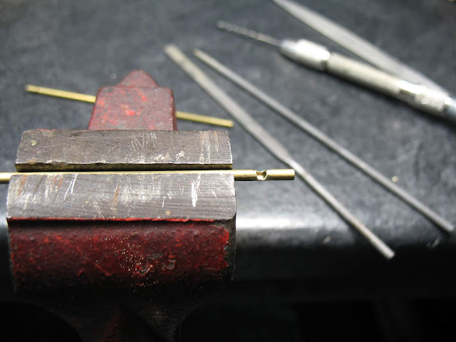
These signals are constructed from K&S brass tubing, the plastic signal targets, LEDs and other plastic bits are from Oregon Rail Supply. The plastic single targets and service platforms are in place at the time of this photo because they are captive between two soldered brass parts on the interlocking signal masts.
The notches visible in the signal masts are for the wiring of the LEDs.
This westward facing photo shows the three Berkshire junction signals in place and operating in the diorama. The interlocking signals indicate the alignment of the Berkshire line switch to the west bound Maybrook main and the alignment of the crossover between the eastbound and westbound Maybrook mains. The automatic block signal in the distance indicates the occupancy of the trackage between the Berkshire junction and Danbury dioramas.
Indicated in red is where the signal station 199 structure will be placed, building this model will be the next project for this diorama.
This is a close up of signal E 36.7, the number on this signal indicates that it is located 36.7 miles east of Hopewell Junction NY on the Maybrook line.
None of these signals are an exact replica of the prototype but will serve a purpose on the layout well.


No comments:
Post a Comment