
Body/chassis core
The body/chassis core and assorted parts from a Branchline Pullman kit will be the starting platform for modeling this car, these parts are also available from Bethlehem Car Works.
The Dudley only had a vestibule on one end of the car, removing one vestibule from the core is the first step. Later in the build a replacement car end will be attached where the vestibule was resulting in the correct 74' 6" length over over the body end sills.
The core with one vestibule removed below.

Car sides
.tif)
To model the correct window/door plan of the Dudley above, the entire center section with windows between the belt rail, letter board and end sills of the donor sides must be removed and replaced with new windows, filler panels and a baggage door in the prototypical configuration.
The remaining vestibule door was also removed completely separating the top and bottom panels of the sides. The door set aside to be reinstalled after the replacement windows, baggage door and filler panels are permanently in place.
For ease of workability while still a separate piece, the vertical rivet detail and fishplates below the beltline has been removed and sanded smooth.

The best way found with hand tools to assure true and parallel surfaces to mount the replacement windows and filler panels between the separated top letterboard and lower side pieces is to lightly fine file the mounting surfaces until these pieces measure consistently in height within .005" end to end.
Care must be taken not to remove to much material so when reassembled with the replacement parts the side height dimension remains the same as an unmodified kit side.

Again for workability it will be easiest to the cut the opening for the baggage doors while side pieces are still individual parts.
The prototype baggage doors below are a simple design and are easily modeled but must be scratch built

There are several things that are unknown about the prototype because of lack of photo verification, specially after the New Haven café-coach conversion being modeled. One example is the baggage door on what became the kitchen side of the car.
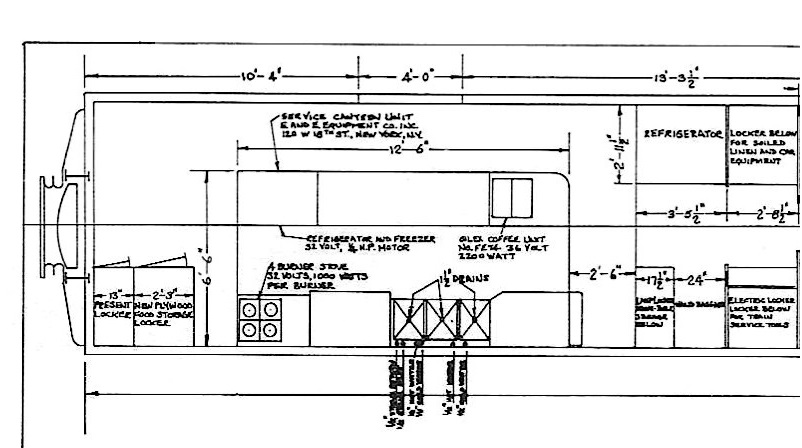
Below is the plan of the once baggage room after the café-coach conversion, the 4' baggage doors originally were directly opposite each other. Sinks and other equipment are now placed flat against the interior wall of the car where the baggage pocket door was on this one side, conjecture would be that this door was removed and a flat exterior panel replaced it but no photo proof has surfaced to date.
Speculating that the kitchen side door was replaced with a plain panel, one door was modeled as originally built and the other with a flat panel.


Before installing the replacement windows and filler panels a way to locate a consistent inset depth of these these parts in relation to the outside surface of the car side is necessary.
A quick temporary jig to achieve this step utilized an aluminum block on hand and some styrene pieces. To function this jig will need to be sandwiched tightly between both cars sides while they are snapped in place onto the core as mentioned before.


No comments:
Post a Comment