Finishing Up
Clearstory Inserts
One other advantage of using the Branchline kit as a core is that the roof clearstory sides are a separate insert part. The kit includes two choices of clearstory side inserts, one that has Ward vents and one that is blank for air conditioned equipment.
The kit inserts have a height of .165", therefore replacing them with a custom insert of ones' choice can easily be fabricated with .156" standard size styrene strips.
The photo below shows the inserts made for the 30' apartment RPO. The area with no windows is made from .040" x .156" plain strips, the area outlining the clearstory windows is also made from standard sized .040" thick styrene strips. The Ward vents were harvested from the kit inserts.
Making a Low Rider
I like Low Riders and have owned a couple, but in this case I am referring to the ride height of the RPO's and the trucks chosen to use under them.
The readily available truck that most resembles the General Steel Casting trucks of the prototype is the #99 top equalized truck from Bethlehem Car Works Kit Bits. These are a three piece metal truck with two side frames and a connecting bolster that screw together.
After assembling these trucks and mounting them under the car, the ride height was measured with a Kadee coupler height gauge and the result showed the car rode higher that it should.
To lower the ride height of the car by the dimension determined from the coupler gauge, that same dimension of material must be removed from the mounting pads on the back side of the truck side frames where the bolster mounts and secures to the side frames with screws.
Notice the thickness of the bolster mounting pads on the back side of the truck side frames of the truck to the right in the photo below. On the left truck the thickness of those mounting pads has been reduced the required dimension therefore lowering the bolster in relation to the side frames and effectively lowering the ride height of the car. The excess material was removed with a razor saw and finished with a fine flat file.
An added bonus to lowering the bolster is that the screw heads are not as visible above the top of the side frames as before.
Rivet Decals.
These RPO's are the first models I tried Archer Rivet Decals on and was pleased with the results.
These rivet decals are individual catalyzed resin droplets on clear decal film. The three dimensional aspect allows them to stand above the surface they are applied to simulating button head rivets. They are applied to a smooth surface before the top coat of paint.
The rows of rivets are cleverly arranged on the sheet to offer several different spacing opportunities by removing them from the sheet ether vertically or horizontally. One can pick out how these rows were removed from the sheet by comparing the sheet to the car side in the photo below.
The completed rivets.
The next two photos demonstrate how the rivets show thru the New Haven Hunter Green top coat of paint.
Below are the completed 15' apartment 45' baggage RPO and the 30' apartment 30' baggage RPO.
I hope some of the construction methods used to build these RPO's may be useful in the building of a model needed for your layout.
Showing posts with label RPO. Show all posts
Thursday, November 19, 2015
Monday, November 9, 2015
Modeling the Berkshire RPO Cars - Part 3
Layering
Layering readily available styrene plastic is a useful method to model three dimensional surfaces in any scale of modeling railroading. The possibilities of this method are endless in the fabrication of structure walls, rolling stock components and in this particular case heavyweight passenger car siding.
A four layer version of this simple method was used to fabricate the replacement sides for the RPO cars needed on the Berkshire Line.
The Replacement Sides
The Branchline coach kit that was used as a core for the RPO's came with car sides that are approximately .075" in total thickness. The replacement sides will need to equal that thickness or be slightly less in order for the replacement sides to fit flush where they meet at the roof line and ends as the stock kit components were designed to do.
A total thickness of .070" was decided on for the replacement sides. The .005" discrepancy between the stock car side and replacement allows a leeway in the assembly process that could be shimmed out if necessary.
Readably available styrene in thicknesses of .010", .040" and .060" where used to build the RPO sides. Where ever possible out of the package stock width styrene strips that closest resembled the prototype dimensions in scale were used to ease and speed construction.
Base Layer
The base layer has a thickness of .010". This layer defines the width and height of the replacement sides. Because this is the foundation layer it is important to make it as square and dimensionally accurate as possible. Visibly, this layer will only represent the door panels and car corners when the sides are completed.
The RPO car corners have a radius, to simulate this radius a strip of .060" 1/4 round was glued vertically on top of the .010" base layer at each car corner to define the two ends of the replacement car sides. The .060" 1/4 round affixed on top of the .010" base layer are now equivalent to the finished thickness of .070".
In the photo below using a straight edge and square, the .060" 1/4 round has been glued at each car end. It is essential that this initial step be accurate and square as possible for a good fit to the car core at the ends and roof line in the end product.
Second Layer
The second layer has many individual parts, is the most difficult and time consuming layer to build. The door stiles, rails and mullions, window stiles and sashes will be outlined by this second layer. All pieces that make up the second layer will be .010" in thickness.
Because of the repetitive process of cutting same sized pieces for the doors and windows and also for the accurate and consistent placement of gluing these pieces onto the first layer, the use of several jigs will greatly speed this step and improve the overall end quality.
The second layer starts with the placement of the bottom door rails. In the photo below a styrene strip of .125" width is used as a jig to accurately locate and glue in place the bottom door rail at the correct height from the bottom of the car side. As a note, all the door rails are cut to a length longer than necessary with the extra length being covered up by the next layer. These rails are simply located right to left by working from a penciled centerline as below.
The next photo shows the two baggage doors and one postal apartment lower door rails glued in place. The initial use of a jig to locate these rails provides an accurate foundation to locate the remaining door parts.
Next photo shows the use of a custom sized .340" jig used to locate the center door rails referenced from the bottom door rail that is already glued in place.
The only purpose of the next photo is to demonstrate that the same .340" jig above can also used to set the stop on the "Chopper" that is used to uniformly cut all the door stile and mullion pieces of that size. Two of the door stiles of this size can be seen temporarily placed on the right door above.
To conclude the placement of the horizontal door pieces the top door rails are again located with a custom sized jig in the photo below. This time the jig is using the glued in place center door rail as a reference. Again, this .280" jig will be used the set the stop on the "Chopper" to cut the door stiles and mullions, this time the ones located between the center rail and top rail.
The below photo shows the placement of the first set of vertical door pieces (mullions). Working from the left using the .060" 1/4 round glued in place at the car end in the first layer as a reference point three different jigs are used to locate the first set of mullions.
The first jig from the left is cut to the height of the car side and .896" wide. The .896" dimension is the distance between the car end and door jamb of the first door. Being the correct size in height and width this first jig will later be used in layer three as a actual permanent piece of the car side.
The second jig in this stack (the one with the two black stripes) is a piece of .040' x .040" styrene strip, this represents the width of the .040" 1/4 round that will be used as a door jamb on the third layer.
The third jig in the stack is custom made width of .239", this is the distance from the door jamb to the first mullion and will be used to glue the first set of mullions in place.
The mullions are now glued in place and will be a reference point for the next set.
On these particular baggage doors there is a .200" space in between the mullions, there is the same .200" space between the mullions and the door stiles. In the photo below the .200" wide jigs are being used to set the second set of mullions. Note to make these .200" jigs they were cut off of one end of the .280" and .340" jigs to insure that they would be exactly the same dimension in height.
Below the .200" jigs were again used to set the door stiles in place and completes this baggage door. The pieces used for the door stiles are wider than necessary, this extra width provides a surface to glue the 1/4 round door jambs to when adding the next layer.
In the next photo, still working from the same car end additional jigs are stacked across the car side to build up the second baggage door. In this view the jigs added to the first two that were used to set up the first baggage door are from left to right,
(1) a jig equal to the width of the baggage door,
(2) another .040" x .040" strip for the door jamb,
(3) a second .896" wide piece again to be used with the third layer,
(4) one more .040" strip for the door jamb and
(5) the .239" jig used a second time to start the build up of the next door repeating the same procedure as the first.
Still working from the same car end additional jigs will be used across the width of the car side to build up the postal door and to outline window openings.
Below is a completed second layer of a car side. All three doors and windows have been outlined, again jigs were used to outline the window openings.
The areas on both sides and under all the doors have been filled in with a layer of .010" thick styrene. The only pieces critical here are under the doors, these strips are .100" in height and leave a .025" slot underneath the bottom door rail where a door sill will be added in the next layer. All these additional pieces will not be visible after the third layer is applied, their only purpose is provide a surface to glue the third layer to. The car side is now has an overall thickness of .020".
On third layer all pieces will be .040" thick. This thickness will give the doors and windows a prototypical inset from the outside car skin.
As mentioned before some of the jigs used in setting up the second layer are now are permanent pieces of the third layer. This includes the large pieces on both sides of the doors and between the center baggage door and windows. The remainder was filed in with pieces sized as needed.
Below is a closer shot of the pieces surrounding the center baggage door. The door sill will be placed in the slot under the bottom door rail and the jambs still need to be attached to both sides of the door in this photo.
The .020" thick door sill has been inserted into the provided slot and the .040" 1/4 round door jambs have been added to complete the door opening in this photo below.
The third layer is now complete and the side now has a total thickness of .060".
The fourth and final layer is a simple task of adding styrene strips for the letter board, the center reinforcement strip and the fish plates under the doors. These strips are all stock sized pieces, .100" for the fish plates, .080" center strip and .188" for the letter board. Additionally .040" pieces were added to the letter board over the doors and .100" over the windows. All the pieces on this layer are .010" thick.
The center strip was placed first. Again jigs were used to accurately space these strips from the bottom edge of the car side.
The letter board was placed next using the top edge of the car side as a reference point. Conversely the bottom edge of the car side was used as a reference point to attach the fish plates under the doors.
This is an overall photo of a completed four layer side. The side is now .070" in thickness and fits to the roof line and car ends as well as the original Branchline sides.
Next post will add some 3D rivet decals and finish up some odds and ends.
Layering readily available styrene plastic is a useful method to model three dimensional surfaces in any scale of modeling railroading. The possibilities of this method are endless in the fabrication of structure walls, rolling stock components and in this particular case heavyweight passenger car siding.
A four layer version of this simple method was used to fabricate the replacement sides for the RPO cars needed on the Berkshire Line.
The Replacement Sides
The Branchline coach kit that was used as a core for the RPO's came with car sides that are approximately .075" in total thickness. The replacement sides will need to equal that thickness or be slightly less in order for the replacement sides to fit flush where they meet at the roof line and ends as the stock kit components were designed to do.
A total thickness of .070" was decided on for the replacement sides. The .005" discrepancy between the stock car side and replacement allows a leeway in the assembly process that could be shimmed out if necessary.
Readably available styrene in thicknesses of .010", .040" and .060" where used to build the RPO sides. Where ever possible out of the package stock width styrene strips that closest resembled the prototype dimensions in scale were used to ease and speed construction.
Base Layer
The base layer has a thickness of .010". This layer defines the width and height of the replacement sides. Because this is the foundation layer it is important to make it as square and dimensionally accurate as possible. Visibly, this layer will only represent the door panels and car corners when the sides are completed.
The RPO car corners have a radius, to simulate this radius a strip of .060" 1/4 round was glued vertically on top of the .010" base layer at each car corner to define the two ends of the replacement car sides. The .060" 1/4 round affixed on top of the .010" base layer are now equivalent to the finished thickness of .070".
In the photo below using a straight edge and square, the .060" 1/4 round has been glued at each car end. It is essential that this initial step be accurate and square as possible for a good fit to the car core at the ends and roof line in the end product.
Second Layer
The second layer has many individual parts, is the most difficult and time consuming layer to build. The door stiles, rails and mullions, window stiles and sashes will be outlined by this second layer. All pieces that make up the second layer will be .010" in thickness.
Because of the repetitive process of cutting same sized pieces for the doors and windows and also for the accurate and consistent placement of gluing these pieces onto the first layer, the use of several jigs will greatly speed this step and improve the overall end quality.
The second layer starts with the placement of the bottom door rails. In the photo below a styrene strip of .125" width is used as a jig to accurately locate and glue in place the bottom door rail at the correct height from the bottom of the car side. As a note, all the door rails are cut to a length longer than necessary with the extra length being covered up by the next layer. These rails are simply located right to left by working from a penciled centerline as below.
The next photo shows the two baggage doors and one postal apartment lower door rails glued in place. The initial use of a jig to locate these rails provides an accurate foundation to locate the remaining door parts.
Next photo shows the use of a custom sized .340" jig used to locate the center door rails referenced from the bottom door rail that is already glued in place.
The only purpose of the next photo is to demonstrate that the same .340" jig above can also used to set the stop on the "Chopper" that is used to uniformly cut all the door stile and mullion pieces of that size. Two of the door stiles of this size can be seen temporarily placed on the right door above.
To conclude the placement of the horizontal door pieces the top door rails are again located with a custom sized jig in the photo below. This time the jig is using the glued in place center door rail as a reference. Again, this .280" jig will be used the set the stop on the "Chopper" to cut the door stiles and mullions, this time the ones located between the center rail and top rail.
The below photo shows the placement of the first set of vertical door pieces (mullions). Working from the left using the .060" 1/4 round glued in place at the car end in the first layer as a reference point three different jigs are used to locate the first set of mullions.
The first jig from the left is cut to the height of the car side and .896" wide. The .896" dimension is the distance between the car end and door jamb of the first door. Being the correct size in height and width this first jig will later be used in layer three as a actual permanent piece of the car side.
The second jig in this stack (the one with the two black stripes) is a piece of .040' x .040" styrene strip, this represents the width of the .040" 1/4 round that will be used as a door jamb on the third layer.
The third jig in the stack is custom made width of .239", this is the distance from the door jamb to the first mullion and will be used to glue the first set of mullions in place.
The mullions are now glued in place and will be a reference point for the next set.
On these particular baggage doors there is a .200" space in between the mullions, there is the same .200" space between the mullions and the door stiles. In the photo below the .200" wide jigs are being used to set the second set of mullions. Note to make these .200" jigs they were cut off of one end of the .280" and .340" jigs to insure that they would be exactly the same dimension in height.
Below the .200" jigs were again used to set the door stiles in place and completes this baggage door. The pieces used for the door stiles are wider than necessary, this extra width provides a surface to glue the 1/4 round door jambs to when adding the next layer.
In the next photo, still working from the same car end additional jigs are stacked across the car side to build up the second baggage door. In this view the jigs added to the first two that were used to set up the first baggage door are from left to right,
(1) a jig equal to the width of the baggage door,
(2) another .040" x .040" strip for the door jamb,
(3) a second .896" wide piece again to be used with the third layer,
(4) one more .040" strip for the door jamb and
(5) the .239" jig used a second time to start the build up of the next door repeating the same procedure as the first.
Still working from the same car end additional jigs will be used across the width of the car side to build up the postal door and to outline window openings.
Below is a completed second layer of a car side. All three doors and windows have been outlined, again jigs were used to outline the window openings.
The areas on both sides and under all the doors have been filled in with a layer of .010" thick styrene. The only pieces critical here are under the doors, these strips are .100" in height and leave a .025" slot underneath the bottom door rail where a door sill will be added in the next layer. All these additional pieces will not be visible after the third layer is applied, their only purpose is provide a surface to glue the third layer to. The car side is now has an overall thickness of .020".
On third layer all pieces will be .040" thick. This thickness will give the doors and windows a prototypical inset from the outside car skin.
As mentioned before some of the jigs used in setting up the second layer are now are permanent pieces of the third layer. This includes the large pieces on both sides of the doors and between the center baggage door and windows. The remainder was filed in with pieces sized as needed.
Below is a closer shot of the pieces surrounding the center baggage door. The door sill will be placed in the slot under the bottom door rail and the jambs still need to be attached to both sides of the door in this photo.
The .020" thick door sill has been inserted into the provided slot and the .040" 1/4 round door jambs have been added to complete the door opening in this photo below.
The third layer is now complete and the side now has a total thickness of .060".
The fourth and final layer is a simple task of adding styrene strips for the letter board, the center reinforcement strip and the fish plates under the doors. These strips are all stock sized pieces, .100" for the fish plates, .080" center strip and .188" for the letter board. Additionally .040" pieces were added to the letter board over the doors and .100" over the windows. All the pieces on this layer are .010" thick.
The center strip was placed first. Again jigs were used to accurately space these strips from the bottom edge of the car side.
The letter board was placed next using the top edge of the car side as a reference point. Conversely the bottom edge of the car side was used as a reference point to attach the fish plates under the doors.
Next post will add some 3D rivet decals and finish up some odds and ends.
Sunday, November 1, 2015
Modeling the Berkshire RPO Cars - Part 2
Finishing the Core
Reinforcing the Undercarriage
The Branchline one piece undercarriage-car ends molding has a natural warp to it out of the box but is straightened when the kit provided car sides and undercarriage center sills are attached in the assembly process. The shortened undercarriage can not rely on the replacement sides to keep it straight, therefore the reassembled undercarriage must be straight before the sides can be attached.
To reinforce the joints and keep the undercarriage straight a piece of .080" thick styrene was glued to the inside floor at the same time the 3 pieces of undercarriage were reassembled, then further strengthened by a piece of 1/4" X 1/4" styrene strip glued to each outer edge as in the photo below.
The doors that are molded into the seperate interior vestibule walls provided with the kit will later be cut out and repurposed as the outer end doors on the finished car. These interior vestibule walls are necessary to have in place to keep the replacement sides perpendicular on the finished car. To replace the walls that come with the kit flat pieces of styrene were cut to the exact size of the kit walls, then glued into the slots where the kit walls would have been located, also seen in the photo below.
Remove the Outer Vestibule Doors
The four outer vestibule doors do not exist on the RPO's and will be in the way of mounting the replacement sides, these doors need to be removed from the core before the car ends can be modified.
The doors are eliminated with three cuts per door using a razor saw. With the car laying on its side the first and most important cut is made using the car end and adjacent door edge as a guide, cut thru the door gap line from the top of the door to the bottom of the door then continue this cut down thru the vestibule floor stopping at the mounting pad and hole for the coupler yoke. Make sure the cut thru the vestibule floor is square with car side because the new end sheet will glue at this cut line.
Next use the door edge on the opposite side of the door as a guide to separate the door from the vertical car side support again cutting from top but stopping this cut at the bottom edge of the door. Finishing up with a third cut flush with the mounting surface of the car sides the width of the bottom of the door to the car end. See photo below.
A Prototype Still Exists
Of coarse this "discovery" was made after the models were already built!
One sunny morning while driving by the tracks of the southern end of the Railway Museum of New England (http://rmne.org/) a familiar roof line was noticed below the road. Sure enough, they have a Bethlehem 30' apartment RPO. This car was originally New Haven RR number 2789. Converted to a work car in 1967, the car is still in work colors and displays New Haven work number W-221. Some so-so photos of the car were taken thru a chain link fence. The photo below is not very good with the sun on the lens but shows the prototype car end needed on the model fairly well.
Modifying the Car Ends
As seen in the photo above the end sheets on the prototype are square to the car sides. The end sheets on the Branchline kit angle away from the car corners meeting with the flat mounting surface for the diaphragm, therefore this angled surface will need to be removed and new end sheets fabricated.
First using a flexible straight edge, a horizontal line is scribed across the width of the car end from the point where the roof curvature meets one car side to the same point on the opposite side of car end.
Second, using the outer edge of the flat diaphragm mounting surface as a guide scribe a line from the horizontal line scribed before to the bottom of the car end. These two scribed lines are where the cuts are made to remove the angled end sheets. The center car core below shows what remains after the cuts have been made to the car ends and a comparison to the stock end to the right.
A piece of 1/4" x 1/4" styrene strip cut to the exact width of the car core is glued in place aligned with the car sides and with outer edge of the cuts that were made in the vestibule floor when removing the doors, see the center core in the photo above. The 1/4" X 1/4" pieces will then serve as a gluing surface for the new end sheets and eventually for the end doors.
The three styrene pieces to form the new car end on each side of the diaphragm mounting surface can be seen orientated in the way that they will be assembled laying in front of the center core above. The end sheet pieces are made from .060" styrene, the same thickness of the original ends. The notched pieces will box in the sides of the diaphragm mounting surface and the thicker tapered pieces complete the bottom of the new ends. The core to the left has all pieces installed completing the new car end.
In the photo below a modified car end is shown on a finished car at the left and compared to a stock Branchline car end at the right.
Part 3 will have a look at the fabrication of the 4 layer styrene replacement sides.
Reinforcing the Undercarriage
The Branchline one piece undercarriage-car ends molding has a natural warp to it out of the box but is straightened when the kit provided car sides and undercarriage center sills are attached in the assembly process. The shortened undercarriage can not rely on the replacement sides to keep it straight, therefore the reassembled undercarriage must be straight before the sides can be attached.
To reinforce the joints and keep the undercarriage straight a piece of .080" thick styrene was glued to the inside floor at the same time the 3 pieces of undercarriage were reassembled, then further strengthened by a piece of 1/4" X 1/4" styrene strip glued to each outer edge as in the photo below.
The doors that are molded into the seperate interior vestibule walls provided with the kit will later be cut out and repurposed as the outer end doors on the finished car. These interior vestibule walls are necessary to have in place to keep the replacement sides perpendicular on the finished car. To replace the walls that come with the kit flat pieces of styrene were cut to the exact size of the kit walls, then glued into the slots where the kit walls would have been located, also seen in the photo below.
Remove the Outer Vestibule Doors
The four outer vestibule doors do not exist on the RPO's and will be in the way of mounting the replacement sides, these doors need to be removed from the core before the car ends can be modified.
The doors are eliminated with three cuts per door using a razor saw. With the car laying on its side the first and most important cut is made using the car end and adjacent door edge as a guide, cut thru the door gap line from the top of the door to the bottom of the door then continue this cut down thru the vestibule floor stopping at the mounting pad and hole for the coupler yoke. Make sure the cut thru the vestibule floor is square with car side because the new end sheet will glue at this cut line.
Next use the door edge on the opposite side of the door as a guide to separate the door from the vertical car side support again cutting from top but stopping this cut at the bottom edge of the door. Finishing up with a third cut flush with the mounting surface of the car sides the width of the bottom of the door to the car end. See photo below.
A Prototype Still Exists
Of coarse this "discovery" was made after the models were already built!
One sunny morning while driving by the tracks of the southern end of the Railway Museum of New England (http://rmne.org/) a familiar roof line was noticed below the road. Sure enough, they have a Bethlehem 30' apartment RPO. This car was originally New Haven RR number 2789. Converted to a work car in 1967, the car is still in work colors and displays New Haven work number W-221. Some so-so photos of the car were taken thru a chain link fence. The photo below is not very good with the sun on the lens but shows the prototype car end needed on the model fairly well.
Modifying the Car Ends
As seen in the photo above the end sheets on the prototype are square to the car sides. The end sheets on the Branchline kit angle away from the car corners meeting with the flat mounting surface for the diaphragm, therefore this angled surface will need to be removed and new end sheets fabricated.
First using a flexible straight edge, a horizontal line is scribed across the width of the car end from the point where the roof curvature meets one car side to the same point on the opposite side of car end.
Second, using the outer edge of the flat diaphragm mounting surface as a guide scribe a line from the horizontal line scribed before to the bottom of the car end. These two scribed lines are where the cuts are made to remove the angled end sheets. The center car core below shows what remains after the cuts have been made to the car ends and a comparison to the stock end to the right.
The three styrene pieces to form the new car end on each side of the diaphragm mounting surface can be seen orientated in the way that they will be assembled laying in front of the center core above. The end sheet pieces are made from .060" styrene, the same thickness of the original ends. The notched pieces will box in the sides of the diaphragm mounting surface and the thicker tapered pieces complete the bottom of the new ends. The core to the left has all pieces installed completing the new car end.
In the photo below a modified car end is shown on a finished car at the left and compared to a stock Branchline car end at the right.
Part 3 will have a look at the fabrication of the 4 layer styrene replacement sides.
Monday, October 26, 2015
Modeling the Berkshire RPO Cars - Part 1
Forward
The scale, car type and dimensional specifications of both the prototype and model only pertain to the HO scale RPO's needed for my railroad. The specifics of my models should be considered secondary to the methods used, ether whole or in part, that could be useful in building a model for your railroad that may not be commercially available.
A Scratch-Bash
To avoid a total scratch building project, the technique used was to scratch build replacement sides, then apply these sides to a kit-bashed available kit.
Starting Point
A Branchline heavyweight coach kit was selected as a core because of its high level of detail, but more importantly is that the sides and roof are separate parts from the one piece molding that combines both the car ends and undercarriage/floor.
Unfortunately the overall length of the Branchline coach kit is too long at approximately 77' and not the exact 60' 11 5/8" over the end sheets dimension of the Bethlehem Steel built RPO's. An advantage though of the core kit being too long is that it can be shortened to the exact length desired. Adjusting the length of the core kit's roof and undercarriage assemblies to the prototype dimension by first removing the correct amount of material, then rejoining the pieces is therefore a prerequisite to the assembly of the replacement sides.
Make a Jig
The easiest and most accurate way to equally shorten the roof and undercarriage is to first make a jig sized to the dimension of the material that needs to be removed from the selected pieces, then using that jig to transfer this dimension to the pieces being physically being shortened.
Defining a jig as a device used to mechanically maintain the correct positional relationship of individual pieces during assembly or the relation between a tool and a piece of work during manufacture. In this case the jig is used to scribe the pieces for cutting. To insure a precise fit of individual parts in the end product, the jig itself should be fabricated as precise as possible. The degree of accuracy is up to the individual, I like to work within a tolerance of + or - .005".
Making and Using a Jig
One simple jig to shorten the car core was made from a flat piece of .010" thick styrene, sized to the width of the roof clearstory by the length (2.172") of material to be removed. Additionally, diagonal lines are marked on the jig to locate the center point of the jig.
For the purpose of positioning the jig onto the roof, small hole has been drilled where the diagonal lines intersect at the center of the jig and a corresponding same size hole has been drilled in the roof where the length and width centerlines of the roof intersect.
The drill bit used to drill both holes is now inserted into the roof, next the hole in the jig is slipped over the drill bit locating the jig properly centered on the roof for scribing.
In the photo below the jig has been squared up to the edges of the clearstory and is being used to scribe lines that mark the parameters of the material to be removed from the center of the roof.
A transverse line (the red line in the photo above) intersecting the center of the jig was also drawn for equally severing the jig into two pieces for use in the next step after the roofs have been completed.
The center section of the Branchline undercarriage has locating holes and fixtures for mounting the kit provided brake components. Retaining this section of the undercarriage makes sense, therefore equal size pieces were cut out of the undercarriage on ether side of the center section.
In the photo below the jig has been cut in half along the aforementioned red line and the now separate jigs have been located against the cross bearers on ether side of the center section. Lines are being scribed on one side of the jigs for cutting and the edge of the cross bearers will be used to position the saw blade on the opposite side.
Cutting the Pieces
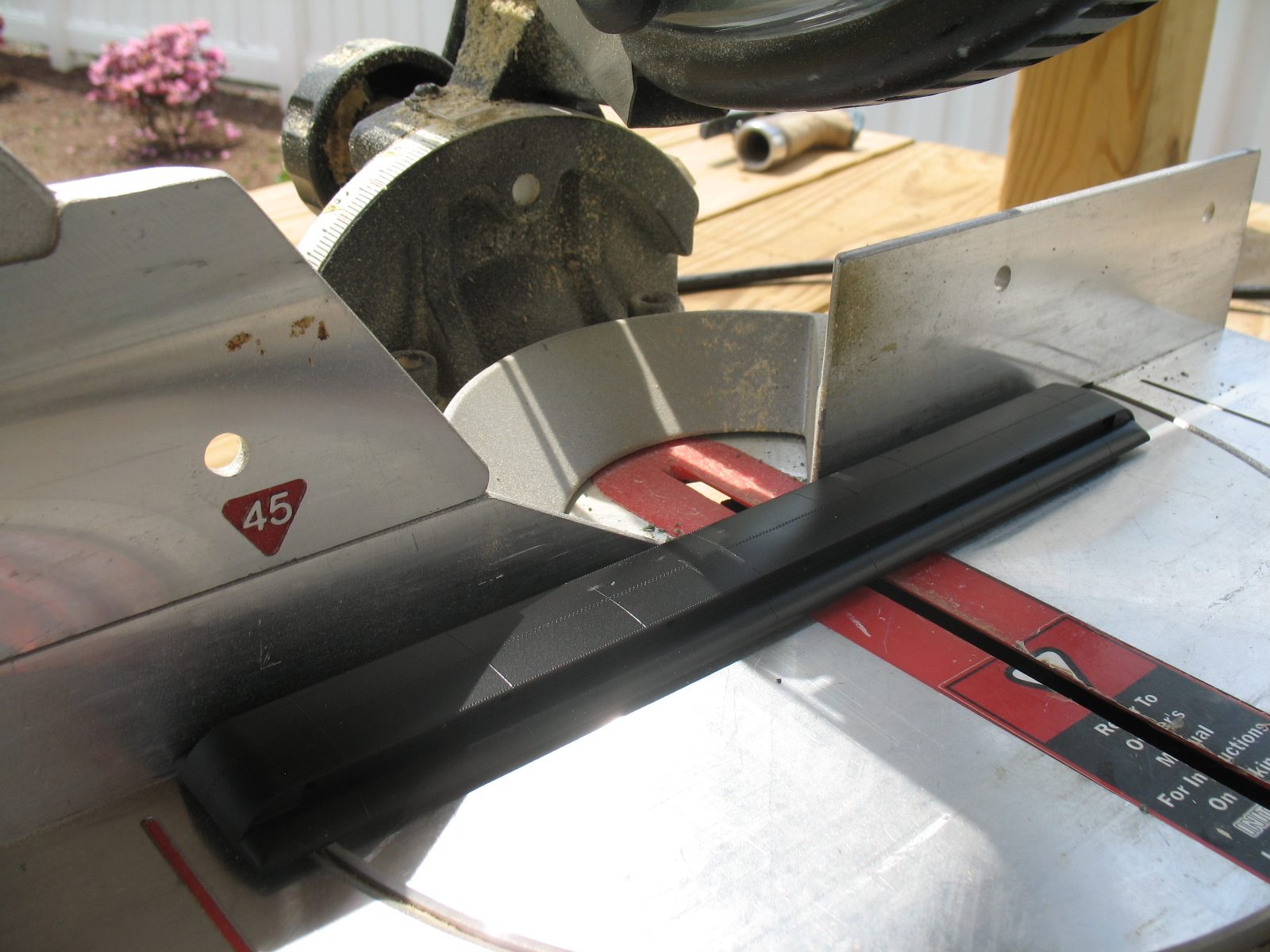
Accurate and clean cuts are necessary for a good fit in the end product. Using the scribed lines as a guide, two cuts were made across the roof using a 10" compound miter saw with a general purpose blade. The use of this type of saw makes very clean precise cuts that are easily rejoined and will require only minimal work before painting.
Position the piece to be cut flat on the table and firmly against the fence.
Cutting to the scribe line closest to the blade first. When the first cut is finished and the with the same side of the roof still firmly against the fence, feed the roof closer to the blade and make the second cut again using the scribe line as the guide.
Rejoining the Pieces.
The pieces are best rejoined on a flat work surface, I use a thick piece of glass taped to a drafting board for this. A straight edge is also necessary for proper alignment, taping a straight edge to the glass as in the photo below works well.
Again making sure the pieces to be rejoined are flat on the glass work surface and both pieces are firmly against the straight edge, a solvent glue for styrene is applied and the pieces are slid together to form a well fitting joint.
The photo below shows a stock size Branchline coach roof is at the top, the length of material removed in the center and the rejoined roof at the bottom.
The below photo again shows the three phases of shortening the undercarriage.
Part 2 will complete the core by modifying the car ends
The scale, car type and dimensional specifications of both the prototype and model only pertain to the HO scale RPO's needed for my railroad. The specifics of my models should be considered secondary to the methods used, ether whole or in part, that could be useful in building a model for your railroad that may not be commercially available.
A Scratch-Bash
To avoid a total scratch building project, the technique used was to scratch build replacement sides, then apply these sides to a kit-bashed available kit.
Starting Point
A Branchline heavyweight coach kit was selected as a core because of its high level of detail, but more importantly is that the sides and roof are separate parts from the one piece molding that combines both the car ends and undercarriage/floor.
Unfortunately the overall length of the Branchline coach kit is too long at approximately 77' and not the exact 60' 11 5/8" over the end sheets dimension of the Bethlehem Steel built RPO's. An advantage though of the core kit being too long is that it can be shortened to the exact length desired. Adjusting the length of the core kit's roof and undercarriage assemblies to the prototype dimension by first removing the correct amount of material, then rejoining the pieces is therefore a prerequisite to the assembly of the replacement sides.
Make a Jig
The easiest and most accurate way to equally shorten the roof and undercarriage is to first make a jig sized to the dimension of the material that needs to be removed from the selected pieces, then using that jig to transfer this dimension to the pieces being physically being shortened.
Defining a jig as a device used to mechanically maintain the correct positional relationship of individual pieces during assembly or the relation between a tool and a piece of work during manufacture. In this case the jig is used to scribe the pieces for cutting. To insure a precise fit of individual parts in the end product, the jig itself should be fabricated as precise as possible. The degree of accuracy is up to the individual, I like to work within a tolerance of + or - .005".
Making and Using a Jig
One simple jig to shorten the car core was made from a flat piece of .010" thick styrene, sized to the width of the roof clearstory by the length (2.172") of material to be removed. Additionally, diagonal lines are marked on the jig to locate the center point of the jig.
For the purpose of positioning the jig onto the roof, small hole has been drilled where the diagonal lines intersect at the center of the jig and a corresponding same size hole has been drilled in the roof where the length and width centerlines of the roof intersect.
The drill bit used to drill both holes is now inserted into the roof, next the hole in the jig is slipped over the drill bit locating the jig properly centered on the roof for scribing.
In the photo below the jig has been squared up to the edges of the clearstory and is being used to scribe lines that mark the parameters of the material to be removed from the center of the roof.
A transverse line (the red line in the photo above) intersecting the center of the jig was also drawn for equally severing the jig into two pieces for use in the next step after the roofs have been completed.
The center section of the Branchline undercarriage has locating holes and fixtures for mounting the kit provided brake components. Retaining this section of the undercarriage makes sense, therefore equal size pieces were cut out of the undercarriage on ether side of the center section.
In the photo below the jig has been cut in half along the aforementioned red line and the now separate jigs have been located against the cross bearers on ether side of the center section. Lines are being scribed on one side of the jigs for cutting and the edge of the cross bearers will be used to position the saw blade on the opposite side.
Cutting the Pieces
Accurate and clean cuts are necessary for a good fit in the end product. Using the scribed lines as a guide, two cuts were made across the roof using a 10" compound miter saw with a general purpose blade. The use of this type of saw makes very clean precise cuts that are easily rejoined and will require only minimal work before painting.
Position the piece to be cut flat on the table and firmly against the fence.
Cutting to the scribe line closest to the blade first. When the first cut is finished and the with the same side of the roof still firmly against the fence, feed the roof closer to the blade and make the second cut again using the scribe line as the guide.
Rejoining the Pieces.
The pieces are best rejoined on a flat work surface, I use a thick piece of glass taped to a drafting board for this. A straight edge is also necessary for proper alignment, taping a straight edge to the glass as in the photo below works well.
Again making sure the pieces to be rejoined are flat on the glass work surface and both pieces are firmly against the straight edge, a solvent glue for styrene is applied and the pieces are slid together to form a well fitting joint.
The photo below shows a stock size Branchline coach roof is at the top, the length of material removed in the center and the rejoined roof at the bottom.
The below photo again shows the three phases of shortening the undercarriage.
Part 2 will complete the core by modifying the car ends
Friday, October 16, 2015
Railway Post Office service on the Berkshire
Authorized service
The U.S. Postal Transportation Service had an authorized space allocation of 15' per scheduled train for the transportation of mail on the Berkshire line in the mid 1950's. Official New Haven Railroad passenger train consist lists of the era indicate the assignment of one 15' apartment RPO car to each of the four scheduled weekday passenger trains over the length of the line. This scheduled mail service was maintained by two RPO's each making daily round trips that originated from opposite ends of the line, one originating at and returning to Grand Central Terminal in New York City and the second originating and returning to the northern Berkshire line terminus at Pittsfield MA.
Equipment
The New Haven had five 15' apartment 45' baggage RPO's on the roster. These 60' cars numbers 2790 - 2794 were all built by Bethlehem Steel in 1930. In the photo below car number 2792 with it's original baggage doors is on the station track at Danbury CT. in the late 30's. This particular car had an electric heater to augment the temperature in the postal section during the cold Berkshire winters on the north end of the line.
Courtesy Bob's Photo
Modeling the Bethlehem built RPO's
Although additional finely designed and manufactured state of the art New Haven Railroad models in all scales have become more readily available as time passes, the lack of available RTR models or kits for some of the railroads rolling stock and most of the railroad owned structures can still offer a pleasurable modeling challenge. As described in the journal introduction, I most enjoy building models of prototypes that are ether unavailable or have not been built before. To date, there are no available RTR models or kits for the Bethlehem 15' or 30' apartment RPO's in HO scale, therefor I decided to scratch-bash this required equipment for my railroad model.
Fortunately for the New Haven modeler there is much information, official drawings and photos available from the New Haven Railroad Historical & Technical Association Inc. thru it's publications and on line forum at www.nhrhta.org The organizations quarterly magazine SHORELINER ran a two part series authored by Wayne Drummond in Volume 26 issues 3&4 featuring all the New Haven postal equipment. These issues, still available from the organization, proved indispensable in the construction of the model RPO's.
The below official New Haven Railroad plan is for the 15' apartment Bethlehem built RPO.
Copyright NHRHTA Inc. Reproduced by Permission
Bethlehem Steel also built ten 30' apartment 30' baggage RPO cars in 1930 for the New Haven. These cars were the same overall dimensions as the 15' apartment cars but with an enlarged postal interior arrangement, visibly different on the exterior with two additional windows and two same size baggage doors on each side.
The below 1965 photo shows that 30' apartment car 2788 is out of service and condemned to the scraper, note the "C" stenciled before the car number. Interestingly, this photo reveals that this car received one flat plywood replacement baggage door in its' serviceable life. This would be a third generation baggage door for this car, but at what date it was installed is unknown.
Courtesy John Kasey collection
At times a 30' apartment RPO was subsututed for the 15' version on the Berkshire. Needing two RPO's for the layout, a decision was made to model one of each version.
Below is the completed 15' apartment 45' baggage RPO model of car # 2792, the second generation baggage doors are appropriate for the mid 50' era.
Next post will describe how the two cars were scratch-bashed.
The U.S. Postal Transportation Service had an authorized space allocation of 15' per scheduled train for the transportation of mail on the Berkshire line in the mid 1950's. Official New Haven Railroad passenger train consist lists of the era indicate the assignment of one 15' apartment RPO car to each of the four scheduled weekday passenger trains over the length of the line. This scheduled mail service was maintained by two RPO's each making daily round trips that originated from opposite ends of the line, one originating at and returning to Grand Central Terminal in New York City and the second originating and returning to the northern Berkshire line terminus at Pittsfield MA.
Equipment
The New Haven had five 15' apartment 45' baggage RPO's on the roster. These 60' cars numbers 2790 - 2794 were all built by Bethlehem Steel in 1930. In the photo below car number 2792 with it's original baggage doors is on the station track at Danbury CT. in the late 30's. This particular car had an electric heater to augment the temperature in the postal section during the cold Berkshire winters on the north end of the line.
Courtesy Bob's Photo
Modeling the Bethlehem built RPO's
Although additional finely designed and manufactured state of the art New Haven Railroad models in all scales have become more readily available as time passes, the lack of available RTR models or kits for some of the railroads rolling stock and most of the railroad owned structures can still offer a pleasurable modeling challenge. As described in the journal introduction, I most enjoy building models of prototypes that are ether unavailable or have not been built before. To date, there are no available RTR models or kits for the Bethlehem 15' or 30' apartment RPO's in HO scale, therefor I decided to scratch-bash this required equipment for my railroad model.
Fortunately for the New Haven modeler there is much information, official drawings and photos available from the New Haven Railroad Historical & Technical Association Inc. thru it's publications and on line forum at www.nhrhta.org The organizations quarterly magazine SHORELINER ran a two part series authored by Wayne Drummond in Volume 26 issues 3&4 featuring all the New Haven postal equipment. These issues, still available from the organization, proved indispensable in the construction of the model RPO's.
The below official New Haven Railroad plan is for the 15' apartment Bethlehem built RPO.
Copyright NHRHTA Inc. Reproduced by Permission
Bethlehem Steel also built ten 30' apartment 30' baggage RPO cars in 1930 for the New Haven. These cars were the same overall dimensions as the 15' apartment cars but with an enlarged postal interior arrangement, visibly different on the exterior with two additional windows and two same size baggage doors on each side.
The below 1965 photo shows that 30' apartment car 2788 is out of service and condemned to the scraper, note the "C" stenciled before the car number. Interestingly, this photo reveals that this car received one flat plywood replacement baggage door in its' serviceable life. This would be a third generation baggage door for this car, but at what date it was installed is unknown.
Courtesy John Kasey collection
At times a 30' apartment RPO was subsututed for the 15' version on the Berkshire. Needing two RPO's for the layout, a decision was made to model one of each version.
Below is the completed 15' apartment 45' baggage RPO model of car # 2792, the second generation baggage doors are appropriate for the mid 50' era.
Next post will describe how the two cars were scratch-bashed.
Subscribe to:
Posts (Atom)


