Reinforcing the Undercarriage
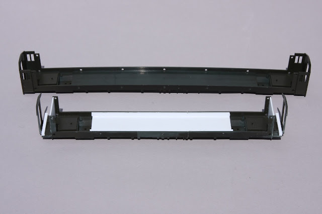
The Branchline one piece undercarriage-car ends molding has a natural warp to it out of the box but is straightened when the kit provided car sides and undercarriage center sills are attached in the assembly process. The shortened undercarriage can not rely on the replacement sides to keep it straight, therefore the reassembled undercarriage must be straight before the sides can be attached.
To reinforce the joints and keep the undercarriage straight a piece of .080" thick styrene was glued to the inside floor at the same time the 3 pieces of undercarriage were reassembled, then further strengthened by a piece of 1/4" X 1/4" styrene strip glued to each outer edge as in the photo below.
The doors that are molded into the seperate interior vestibule walls provided with the kit will later be cut out and repurposed as the outer end doors on the finished car. These interior vestibule walls are necessary to have in place to keep the replacement sides perpendicular on the finished car. To replace the walls that come with the kit flat pieces of styrene were cut to the exact size of the kit walls, then glued into the slots where the kit walls would have been located, also seen in the photo below.
Remove the Outer Vestibule Doors
The four outer vestibule doors do not exist on the RPO's and will be in the way of mounting the replacement sides, these doors need to be removed from the core before the car ends can be modified.
The doors are eliminated with three cuts per door using a razor saw. With the car laying on its side the first and most important cut is made using the car end and adjacent door edge as a guide, cut thru the door gap line from the top of the door to the bottom of the door then continue this cut down thru the vestibule floor stopping at the mounting pad and hole for the coupler yoke. Make sure the cut thru the vestibule floor is square with car side because the new end sheet will glue at this cut line.
Next use the door edge on the opposite side of the door as a guide to separate the door from the vertical car side support again cutting from top but stopping this cut at the bottom edge of the door. Finishing up with a third cut flush with the mounting surface of the car sides the width of the bottom of the door to the car end. See photo below.
A Prototype Still Exists
Of coarse this "discovery" was made after the models were already built!
One sunny morning while driving by the tracks of the southern end of the Railway Museum of New England (http://rmne.org/) a familiar roof line was noticed below the road. Sure enough, they have a Bethlehem 30' apartment RPO. This car was originally New Haven RR number 2789. Converted to a work car in 1967, the car is still in work colors and displays New Haven work number W-221. Some so-so photos of the car were taken thru a chain link fence. The photo below is not very good with the sun on the lens but shows the prototype car end needed on the model fairly well.
Modifying the Car Ends
As seen in the photo above the end sheets on the prototype are square to the car sides. The end sheets on the Branchline kit angle away from the car corners meeting with the flat mounting surface for the diaphragm, therefore this angled surface will need to be removed and new end sheets fabricated.
First using a flexible straight edge, a horizontal line is scribed across the width of the car end from the point where the roof curvature meets one car side to the same point on the opposite side of car end.
Second, using the outer edge of the flat diaphragm mounting surface as a guide scribe a line from the horizontal line scribed before to the bottom of the car end. These two scribed lines are where the cuts are made to remove the angled end sheets. The center car core below shows what remains after the cuts have been made to the car ends and a comparison to the stock end to the right.
The three styrene pieces to form the new car end on each side of the diaphragm mounting surface can be seen orientated in the way that they will be assembled laying in front of the center core above. The end sheet pieces are made from .060" styrene, the same thickness of the original ends. The notched pieces will box in the sides of the diaphragm mounting surface and the thicker tapered pieces complete the bottom of the new ends. The core to the left has all pieces installed completing the new car end.
In the photo below a modified car end is shown on a finished car at the left and compared to a stock Branchline car end at the right.
Part 3 will have a look at the fabrication of the 4 layer styrene replacement sides.


Your work is inspiring, Joe. Thanks for sharing it - and I look forward to future posts.
ReplyDeleteCheers!
- Trevor (Port Rowan in 1:64)