Showing posts with label Headend Cars. Show all posts

Friday, February 8, 2019

Boston & Maine Baggage - Express Car 3280 - Model Finished

Modeled Boston & Maine #3280

Building a model of this converted B&M baggage express car has been an interesting adventure and learning experience starting from the 1958 J. W. Swanberg photo taken in Danbury Connecticut. New Haven EP-3 # 352 was obviously the primary focus of this photo but coupled to motor #352 was an unidentifiable baggage express car with a vestibule on only one end. Thinking that this Non-Haven car would add operational diversity from the home road baggage express cars piqued an interest in building a model of this car.


Fortunately several knowledgeable people answered my blog and NHRHTA forum questions for the identity of this car, they are named in part one and I once again thank them for their contributions.

Photo and dimensional evidence of the prototype car is very limited, what remained unknown is conjecture on my part but I hope finished end product below can be considered a credible model of the prototype.


What is going on in this photo?

The below photo attempts to recreate the original operational movement captured in the 1958 J. W. Swanberg photo.

New York Grand Central Terminal to Pittsfield Massachusetts Train #140 The Mahaiwe has arrived at the end of the Berkshire electrified track at Danbury Connecticut at 10:19 AM.

Motor #352 and Harlem River to Danbury express car #3280 are cut off from train #140 and are pulling forward to clear the crossover from track #6 to track #8, once clear the express car will be backed thru the crossover onto track #8 to a location near the station for unloading. Motor #352 will then pull forward to motor service further east in Danbury yard.


Train #140 continues with diesel power departing Danbury station at 10:29 AM for the remaining 89 mile run to Pittsfield, MA.


Thursday, January 24, 2019

Boston & Maine Baggage - Express Car 3280 - Part 4

Car Ends

When originally built for the C&O this baggage/express car had two different design ends. The vestibule end as seen below in the 1958 J. W. Swanberg photo had a design that appears to be the same as the Branchline coach kit that is the core model for this scratch-bash and will not be changed in this build.

Also note the lavatory vent on this end of the car. Most of the B&M converted baggage/express cars had the lavatory facility constructed on one side in a center location of the car. It appears that the two ex-C&O converted cars retained the original location of the Women's lavatory for this purpose instead of constructing a new lavatory in the center of the car..


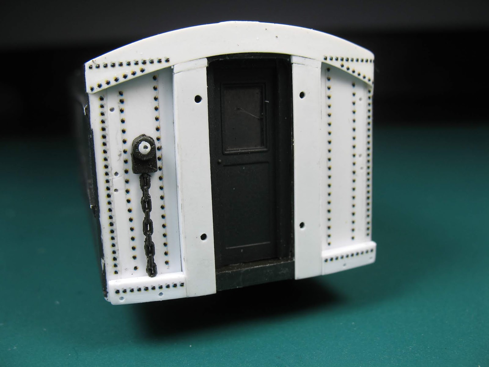
The opposite car end was originally the RPO end when built for the C&O, this had a different design as below. This end will have to be scratch-bashed.


The below photos show the development of constructing this end with sheet styrene and strips.

Below the unnecessary parts of the Branchline end have been removed leaving a foundation for a new styrene end.


Two styrene strips on each side box in the diaphragm mounting surface.


End sheets have been added to each side of the diaphragm mounting surface and an upper panel has been mounted. The two small filler pieces between the diaphragm surface and the upper panel are there because a height mistake was made when cutting the diaphragm surface pieces, hopefully won't show when sanded smooth and the end is completed, painted and diaphragm mounted.   


An end door is now in place, this came from the kit's inside vestibule wall. The window was sheeted over, maybe this should have been left as a window for emergency egress as B&M practice with the baggage doors? Not having a prototype photo of the brake gear, the gear and chain were harvested from the Athearn car that the roof came from. All holes for hand grabs are also drilled.


Archer rivet decals are again used, the rivet pattern is more prototypical here that the sides. The diaphragm and roof are trial fit.


The Roof

In the photo below that was taken after the B&M conversion it appears that the roof most likely retained the original 10 Garland vents as when built for the C&O. Drip rails have been added over the baggage doors.


Because of the overlapping roof sheets of the Athearn roof, slots need to be cut into the raised roof sheets for mounting the drip rails.


All the roof details are in place in the below photo. The Garland vents are from Custom Finishing Models, the lavatory vent is from the Branchline kit. Not enough brass bar stock was on hand so styrene was substituted for the side drip rails. Grabs and ladder rests are also in place here before painting.


I noticed in the prototype photos that the stirrup steps below the baggage doors have a 45 degree bends above the second rung and are mounted underneath the car. To be consistent with the other baggage cars on the layout steps from Bethlehem Car Works were again used and 45 degree bends were added to the otherwise flat steps.


Below is the finished car body painted B&M maroon.


Next time will show the finished car.

Wednesday, January 2, 2019

Boston & Maine Baggage - Express Car 3280 - part 3

Car Sides

The sides of car #3280 are plain in design and could be fairly uncomplicated to model with layers of styrene.

A B&M mechanical department document indicates each car side of #3280 has 2 door openings that are 8' wide. An enlargement below of the car circled in the opening photo of part 1 shows that this car has 2 sliding wood construction doors per opening.


The above photo also shows this car had reinforcement plates under each door opening, a belt rail and what appears to be a batten strip separating the letterboard area from the lower part of the sides.

It is my understanding that it was standard B&M practice on all converted baggage/express cars that each baggage door had one window large enough for a person to egress in an emergency. The photo below of a B&M converted Pullman clearly shows the one window large enough for that purpose per door, this is the wooden door design that will be used on the model.


Above are the known and photo evidence details of B&M #3280 car sides. What is not known for modeling is the placement of the baggage door openings and any rivet pattern on the car sides. The 20' to center door opening placement in the drawing below is only conjecture but this measurement looks like it could be near to correct and will be used on the model.


Making the Sides

The sides will be modeled with a four layer styrene system used on other rolling stock previously built for the layout. The photo below shows the first 2 layers.

The base/1st layer is .010" thick styrene cut to the length and height dimensions required for the sides. A strip of .060" 1/4 round strip styrene is glued to one end only of each base layer for modeling the car corner posts, an existing vestibule door jamb will frame the opposite ends when mounted to the Branchline core.

The 2nd layer is also .010" thick. This layer covers the base layer and will form the exterior surface of the doors that will be visible on the finished model. All other areas of the base layer will also be covered with .010" filler pieces that will be unseen on the finished model after the 3rd layer is applied over them. A .025" slot will be left open under each door, this will be for a .020" thick door sill to be mounted later.


There is more on this blog about layering and how the doors were modeled using styrene strips and jigs, this method was also used when the RPO cars were built and can be seen there.

Below are a sample of the many parts that comprise a door, these are just the vertical pieces that will be used when assembling the doors on the second car side.


The 3rd layer will represent to outer surface sheets of the sides, these side sheets are all .040" thick.

Each side sheet has 3 basic parts, the upper side sheet, lower side sheet and a .015 x .060 upper belt rail piece. The .060" wide surface of the upper belt rail piece will be glued sandwiched between the upper and lower sheets, leaving .015" x .020" protruding further out from the side sheets to represent the top of the belt rail.

The .010" thick batten strip and lower belt rail piece are actually parts of the 4th layer of detail. The lower belt rail piece will be glued directly under the upper belt rail piece completing the belt rail and the batten glued were needed.

One of the six completed side sheets is at the top in the below photo.


Below are both finished sides.

Pieces of .040" thick strip styrene fill in between the side sheets above and below each door and .040" 1/4 round strips make up the door jambs to complete the 3rd layer.

The 4th layer door opening reinforcement plates are in place under each door, these are also .010" thick. The door sills will be added later before painting.

The windows openings will be cut out and mounting holes will be drilled for all hand grabs before the sides are attached to the Branchline core.

Not having photographic proof of the rivet pattern on the prototype, a generic rivet pattern was applied with Archer rivet decals.


Next time will finish the car ends and roof.

Friday, December 21, 2018

Boston & Maine Converted Baggage - Express car 3280 - Part 2

Selecting Core Parts

This model build is essentially a scratch-bash, applying scratchbuilt sides to a kit-bashed readily available core kit and roof from another.

The Branchline heavyweight coach kit was once again selected as the base core because the sides and roof of this kit are separate parts from the one piece molding of the undercarriage/floor and car ends making it much easier from the beginning to replace the sides and roof with one's needed to replicate the B&M car. The length of the chassis/floor molding from the Branchline kit can also be shortened quite easily for adapting to the shorter lengths of many headend cars.

The idea in selecting a roof for this build comes from Ryan Mendell who successfully used the venerable Athearn heavyweight coach round roof on his beautifully built Canadian National RPO. This roof is easy to obtain on the used market and will replicate the round roof of the B&M converted baggage-express car well. Two second hand Athearn coach bodies were obtained from The Hobby Gallery which is always a great source for used equipment and new offerings.

The Roof

The roof from the Athearn round roof coach needs to be removed from the one piece car body molding before it can be used for this build. Also the as molded roof of this coach is not long enough to model the B&M car and therefore needs to be lengthened, I decided to add length to both ends with equal sized pieces from a second Athearn car body.

After determining where to make the cuts to finish with a roof length equal to the prototype, both of the Athearn coach car bodies had a slot cut thru the roof at each end on a general use compound miter saw. The one being cut below will become the center portion of the finished roof.


The second roof had similar slots cut, the equal length end pieces below will be grafted to the center section resulting a correct prototypical length roof for the model.


For safety reasons cutting all the way thru the car bodies on the saw would require a firm interior support, not wanting to take the time necessary make a support equal to the interior width of the car body was the reason for cutting slots only thru the roof. After the slots were cut thru the roof the car ends were easily removed by finishing the cuts with a pair of side cutters. Both car sides were then removed from the remaining portion of the roof by scribing a line were the roof meets the sides, then snapping off the sides much like the scribe and snap method used when working with styrene.


Below is the finished prototypical length roof.


Undercarriage/Floor & Ends

The Branchline core undercarriage/floor is to long and will need to be shortened to the 75' 5 3/4" overall length of the prototype car.

One car end retains the as built vestibule of the original prototype C&O car, this end of the Branchline core will be left as originally molded. The opposite end of the prototype car has no vestibule, this end will be shortened between the bolster pad and the car end to achieve the correct prototype length.

For the correct placement and prototype distance between the truck centers the bolster pad on the end being shortened will be turned 180 degrees at the same time the end is being cut to length. The photo below compares the shortened car length and rotated bolster pad on the left to an as molded Branchline part on the right.

Extreme care must be taken when bonding these 3 pieces back together so the car floor and sides remain in alignment as they did with the factory molded part, to ensure proper alignment a straight edge clamped to both sides of the interior floor during the gluing process guaranteed a straight and level end result. 


The prototype car has a different non-vestibule car end design than the vestibule end, to model this other design the car end will be kitbashed to appear as the prototype. In preparation to correct this end the unnecessary molded parts of the shortened end section seen below were cut away before rebonding this end to the rotated bolster and core undercarriage/floor.


Below is the completed non-vestibule end of the core base of the model.

To ensure that the outer face of the car body end will remain plumb to the base undercarriage/floor styrene supports sandwiched between the interior vestibule wall and the car end were glued in place. For a good end result these supports should be precise and were made to a +/- .005" tolerance. These supports will not be seen after the end door is in place.

Also note the sturdy styrene strips glued in place on both sides to reinforce the glue joints of the 3 now connected pieces of the core, these strips permanently take the place of the straight edges that were clamped on for proper alignment during the glue curing process.


One more modification is needed to complete the two core pieces. The Athearn roof ends must be arched to coincide with the arch at the top of the car body ends. The below photo shows this arch has be cut into the roof end, still much sanding left to finish this end for painting but that will come later in the final stages of the build.


Next post will build the car sides and non-vestibule car end.

Saturday, December 8, 2018

Boston & Maine Railroad Converted Baggage-Express Cars 3280 - 3281

B&M  Baggage-Express Cars 3280-81

The Boston & Maine Railroad purchased several surplus cars in the early 1950's to convert to all steel baggage-express cars replacing the railroads ageing wooden bodied baggage-express roster.

B&M road numbers 3280 & 3281 are two of these converted baggage-express cars, one of which is circled in the photo below.


What originally piqued an interest in these B&M cars was the 1958 J. W. Swanberg photo below that had been used for reference when constructing models of New Haven EP-3 motors. Noticing that the baggage-express car behind the EP-3 in the photo had a vestibule on only one end verified this unusual arrangement was not a New Haven Railroad prototype.

Having photographic proof that this foreign road express car was in Danbury during the era of the layout, a model of this car is desirable for an occasional appearance when operating for a visual diversity from the usual home road express cars.


In the photo above there is no readable lettering to determine the railroad ownership of this car. A post on this blog was published asking for help in identifying this car and several knowledgeable persons kindly reciprocated.

Chesapeake & Ohio Origins

B&M cars 3280-81 were originally part of a 1930 Chesapeake & Ohio Railroad five car RPO/baggage/passenger combination car order built by St. Louis Car Company becoming C&O road numbers 400-404. Number 402 is shown in the as built 15' RPO/baggage/36 seat passenger configuration below.


Conversion to Baggage-Express Cars and use by the B&M

The C&O sold cars 403-404 to the B&M in January 1950 where they were converted to baggage-express cars while retaining the vestibule on one end, this is the configuration seen in the two lead photos.

The converted car retains a lavatory vent seen in the Swanberg photo, so the assumption is that the cars could have been used in messenger service. B&M messenger cars had the lettering "equipped with water system" and a star under the Railway Express Agency lettering on the car sides but this is undetectable in ether of the two photos of the converted cars.

Suggestion is that under B&M ownership these cars may have been regularly used for a time on the international train the "GULL" a 24 hour train between Boston and Halifax, Nova Scotia. Custom agents boarding these cars for inspection during border crossings may have favored these cars because of their vestibules ease of entry/exit.

Express from the B&M with a destination for the REA terminal in the Bronx, NY could have been routed over the New Haven thru the connection with the B&M at Springfield, MA. Speculation is while one of these cars was at the Harlem River Terminal empty it was loaded for express to Danbury where it was photographed by J. W. Swanberg in 1958.

Enough Information to Build a Model?

I am only aware of the two photos shown above of these cars after their conversion to baggage/express cars by the B&M, but these two photos do show both sides of the car and part of the vestibule car end. The photo of the car in the original C&O configuration shows the opposite or RPO/baggage end which differs in construction from the vestibule car end. All three show the roof venting details.

The combination of the three photos, dimensional data from a C&O drawing and with information sent by the respondents to my request for help about these cars I feel this provides sufficient speculation to build a creditable model.

The side view Drawing below is what I speculate the model should look like. The dimensional data for the truck centers, overall lengths over the platforms and end posts are derived from a C&O mechanical drawing therefore factual. The 8' wide baggage door openings with double doors are also factual information gleaned from a B&M Mechanical Department document. The dimension to centerline of the baggage door openings from the end posts is conjecture on my part.


Model construction of one of these B&M baggage-express cars will begin with the next post.

Thank You!

A special thank you to John Horvath, Tom E. Thompson, Dave Varholy and Ed Shoben. Without the generous help that these gentlemen took time to provide, building a model of this car for my layout would not be possible. Thank you all!