Showing posts with label Modeling a DEY-2 Switcher. Show all posts

Wednesday, July 20, 2016

Modeling The New Haven DEY-2, Part 5

The Finishing Details

A method to model the louvers on the cab plus the two different widths of louvers on the side of the long hood and were a deterrent that had delayed starting this model for some time. A breakthrough in the thought process came when I used .005" styrene to re-side a Proto 100 DL-109 and discovered how easy it was to emboss detail into the thin styrene by placing it over a detailed surface and then transferring that detail into the styrene by rubbing it with a toothpick.

The below photo shows a piece of .005" styrene clamped to the side of an Atlas RS-1 body shell, the louver detail has been embossed into the styrene with a tooth pick. These louvers where cut out and glued to the side of the long hood in the appropriate places as necessary.

Click to enlarge photos

A die was necessary to emboss the wider louvers required for the sides of the long hood. Using the same louvers as above, this section of louvers was removed from an other shell and the two were spliced together to form a die for the wider louvers. see below.


This model was built before resin rivet and louver decals were available, maybe a decal for this detail is available today.

Outside mounted hinge detail for the doors on the sides of the long hood much like the hinge on the RS-1 in the photo above were required.

The photo below show brass wire glued to .010" styrene strips to make the single door hinges at top and the double door hinges below. Initially the wire was cut longer that necessary to facilitate ease of handling when gluing and was cut even with the edge of the strips after the glue had cured.


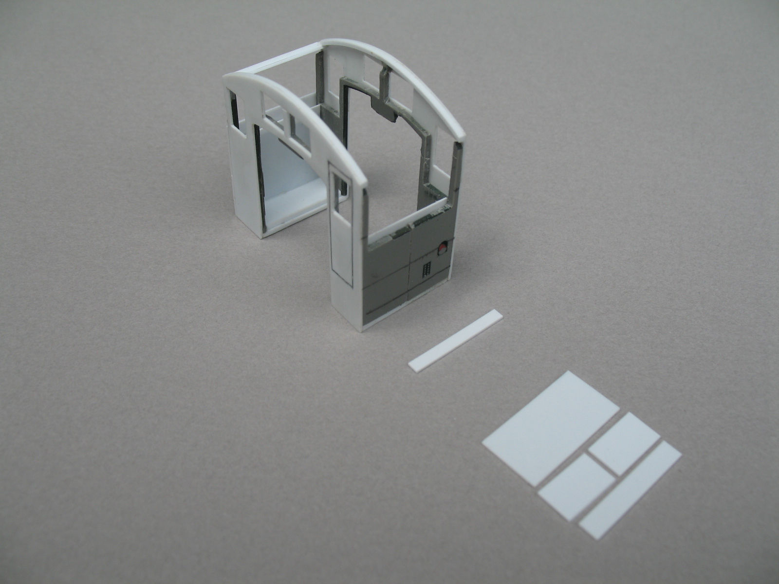
The photo below shows the underside of the components that make up the two access hatches that are located on the top of the long hood.


This photo shows the underside of the hatch components after assembly. The two long strips will be the contact/glue surface to mount the hatch assembly to the top of the hood.


To make these glue strips fit the arch of the hood, the now upright hatch assembly was rubbed back and forth over a fine piece of sandpaper that was draped over the top of the hood until the arch of the hatch mounting strips was the same as the hood making full contact glue strips.
 

Below the hatches have been glued to the hood top. In the same photo note that both the narrow and wide louvers have been attached to the side access doors along with the single door hinges.


Brackets to hold the front and rear headlights were made from a piece of brass channel. Two lengths of brass wire were soldered to the channel and will mount the brackets into matching holes drilled into the ends of the hoods as seen below.


The pilots are also made from styrene. For strength, the footboard mounting brackets were made from brass bar stock. A completed pilot and a set of components can be seen below.


Below a pilot and a buffer have been mounted to the front of the flat slab baseplate that the cab and hood superstructure will sit on, the pilot components lay in the foreground.

The steel plate slab of the prototypes baseplate was 1 1/2" thick, .020" styrene was used to represent that on the model. The base plate was carefully cut out just enough to clear the motor, gear tower assemblies and parts of the original chassis that protrude above the mounting surface of the styrene base plate.


Below are the component pieces that were used to re-side the SW9/1200 trucks to make them look more like the welded trucks on the prototype.

The truck sideframe at the top is an unaltered Proto SW9/1200 piece, the one below that has the brake cylinder and brake shoe assemblies removed to make clearance for the styrene pieces to be glued onto the sideframe and the third sideframe has all the pieces attached. The springs below come from old freight trucks, the spring parts were attached where needed, see the six springs peaking out below the larger styrene piece that makes up the re-sided side frame.


Below the finished trucks are attached to the chassis.


In the following two pictures some of the finishing details can be seen attached to the switcher.

Two Access panels are on the front of the long hood.
Three angle iron steps for roof access are on both hood ends.
All louvers including the ones on the cab sides are in place.
Headlight brackets.
Door hinges installed.
Side tanks installed, these are made from styrene tube with the ends caped, then tank sides resided with .005" styrene with rivet detail embossed.
Exhaust stack made from brass tube.
Sand storage tank clean out plugs, Cal Scale bearing caps used for this.
Pilots installed.
Radiator fan shroud, this is from a Stewart RS-3 Flat kit. May be available from Bowser today.
Lift rings, Detail Associates.


Below are the pieces that make up the end steps. These are made oddly enough from EMD F-7 number boards. I had bought two used Kato-Stewart F-7's to repower a pair of poor running Geeps, the bodies were un-needed and these number boards were a separate casting and very strong rigid pieces so I thought that they would be a great basis for the end steps.

The few added pieces of styrene shown were all they needed to make a fair representation of the curved bottom end steps of the prototype.


The shape of the side plates of cab steps were taken from the GE drawing. A finished step and the component parts to make the second set can be seen below.


The next set of photos taken during the painting process show cab steps and some of the other final details like the whistle, grab irons and assorted details on the top of the short hood in place.


This picture has the end steps and hand rails installed. The hand rail stanchions also come from the Stewart RS-3 flat kit, the hand rails are made from brass wire. The painted trucks and side tanks with straps show well in this some what off color photo of the completed model below.

 
In conclusion, this was a fun and challenging build that gave me an opportunity to explore some new modeling techniques. My wish is that this series of photos may inspire someone else to build a model of this locomotive, possibly in a larger or smaller scale, or the very cool Bangor & Aroostook Railroad version, or maybe just some small aspect used to build this model that could be helpful in building a model you need.

Now, I wonder if some decoder manufacturer has a sound file for a 1936 Cooper-Bessemer 660 HP non-turbo prime mover?!

Although New Haven DEY-2's were never used on the Berkshire and gone before my modeling era, this one will be occasionally at home switching cars on the layout in Danbury as seen below in front of the nearing completion Danbury freight house model. The freight house will be the subject of a future posts.


Monday, July 11, 2016

Modeling The New Haven DEY-2, Part 4

The Short Hood

The short hood is to long! Part one noted that the Proto 2000 SW9/1200 power chassis was one foot to long, so somewhere the superstructure (new body shell) of the modeled DEY-2 would have to be one foot longer too.

This one foot discrepancy was split up between the cab and the long hood, adding six scale inches to each. Originally I thought that splitting the size difference equally between the three body components, the long hood, short hood and the cab would be best to make the new shell come out proportionately correct. The size of the roof top radiator fan shroud that was being planed for use dictated that at least six scale inches would have to be added to the length of the short hood so I decided to add the same to the cab too and leave the long hood the correct scale length. I did this because the prototype short hood and the cab are the same length therefore making them the same length on the model would be the best proportionately.

As a starting point for re-siding the short hood, not to much is left of the Atlas hood in the photo below. The hood front was removed when shortening the hood in the beginning and a large cutout in each side for the radiator air intake shutters to be inset has been opened up. The white styrene pieces in the photos are to reinforce the sides and be a gluing surface for the radiator shutter assembly, these are glued to the inside of the shell. The slot to receive the interlocking tab that locates the cab to the hood can be seen in the second photo.

Click to enlarge photos


Below is the radiator intake shutter assembly. A piece of stock sized clapboard siding that is the closest match to the number of louvers needed was used to represent the shutters, four pieces of strip styrene was used to make the surrounding frame. Not seen in this photo, a slot to receive the sand filler hatches was cut into the front edge of both sides in this step before any of the re-siding styrene was added.


The short hood was re-sided using the same materials and methods as the long hood shown in part 2. The components of the sand filler hatches can be seen in this photo, it is basically a four sided box made with strip styrene and a fifth piece scored on the back then bent to an angle without breaking it in half, then inserted into the box.

In the bottom photo, two strips of styrene were glued to the inside reinforcement piece to shim out the shutter assembly to be flush with the sides.


One of the most difficult steps in building this model was drilling the series of holes in top of the frame surrounding the shutters. I found it very difficult to hand drill these holes in a straight line and evenly spaced to one and other. Several attempts were made before I was able to get two pieces I was remotely happy with. The holes are one short of the prototypes 14 and can be seen in the photo of the almost completed hood assembly below.


Below are two photos of the completed short hood and cab together. The short hood has two bolt on service panels located on the front panel, they are not seen in these photos but will be shown in later in this series.


The three components that make up the DEY-2 body shell are shown interlocked together in the photos below.


The gray radiator fan shroud on top of the short hood in the above photos is from an Alco RS-3 model and will be described in the next segment along with a look at the details needed to finish this model.
     

Tuesday, July 5, 2016

Modeling The New Haven DEY-2, Part 3

The Cab

The part 1 photo below showed that the Atlas RS-1 cab had been shortened to the length needed.

Click to enlarge photos

The side to side curvature of Atlas roof has radius that is to sharp, a new roof needs to be made that will match the curvature of DEY-2. Below the entire cab roof has been removed, not much remains of the Atlas cab halves.


A scratch built cab was considered at this point, but the thick rigid plastic that remains from the Atlas cab still offers a strong understructure with defined corner posts for the window area and the ability to interlock with the Atlas hoods using the original tabs under front and rear cab windows, therefore the parts were retained for re-siding.

 A new base plates were made for the cab, this helps in aligning the two halves together for gluing and also raises the cab to the same height as the long hood that was raised in the beginning of part 2. This photo also shows the retained original interlocking tabs that will locate the cab to the long and short hoods.


Below are the two pieces that will re-side the front and rear of the cab. The curvature of the cab roof was traced from the GE drawing. The windows were marked and cut out, the gap surrounding the doors was scribed into the pieces.

A styrene template was made by tracing with a scribe the front panel of the long hood completed in part 2. A centerline was marked on the template then matched with the centerline marked on the pieces below to accurately cut out the opening for the cab to slip over the re-sided hoods.


A gluing surface that follows the correct side to side roof curvature will be needed to affix the new roof at the front and rear of the cab. Below styrene strips wide enough for that purpose are glued to the inside top of the front and rear cab pieces following the curvature that was cut into these pieces and held down with weights till cured. When cured the strip was cut off flush with the cab sides.


Here the new cab ends have been glued to the under structure.

The pieces to re-side the cab sides are also showed below. Note that a piece of styrene has been glued to the inside of the cab sides, this reinforces the joint were the two cab halves were rejoined and glued.


Here the side pieces are glued in place. The piece glued in place at the top of the side window opening is tilted to match the curvature of the roof, it will serve as a gluing surface for the roof panel were it meets the side of the cab, the piece glued to it directly underneath is a gluing surface for the top of the window frame.


The next photo shows the window openings in place and the pieces necessary for that below.


This photo and the one above show the completed cab without the roof panel.


Below is the roof panel, it is also made from .010" styrene. The side to side length of this piece including the downward bend on both sides was figured out before hand. The curvature of the cab roof overhang at both the front and rear of the cab was also figured out before hand. The overhang curvatures were marked on the panel with a French Curve then cut into the roof panel with a very sharp pair of scissors before the side to side curvature was worked into the panel. This overhang curvature can be seen on the finished model and on the drawing in the opening photo in part 1.

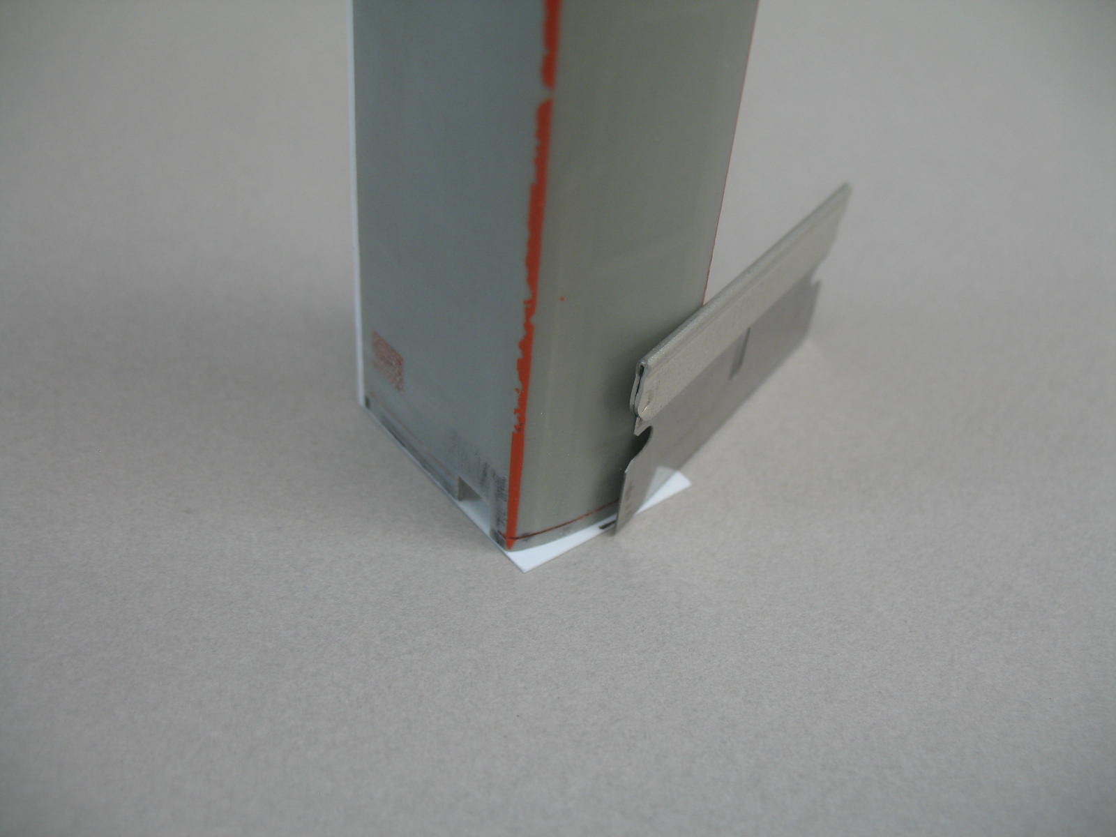
The side to side curvature was worked into the piece till it would hold the correct radius by moving it back and forth over a smooth metal rod that was clamped into a vise, much like you would hold a rag and run it back and forth over the top of a shoe when polishing. After the curvature was set into the panel, the downward bends over side windows were bent from the inside. Laying the panel upside down the edges of two single edge razor blades were used to make bends, one blade to hold the panel down on a flat surface at the bending line and the other to bend the material up at the bending line.

The roof was not permanently attached the cab until the paint work was completed and the glazing installed.


Next post will look at the short hood.

Monday, June 27, 2016

Modeling The New Haven DEY-2, Part 2

Forward

This is the first model that I tried to record the construction progress in a photo log. I am a modeler first, not a photographer! I get so interested in the modeling itself that I often forgot and still do forget to take photos of some of the steps in the model building process.

When this model was built I had just acquired my first digital camera. Many of the photos reflect my inexperience with this simple point and shoot camera, the photos do get somewhat better as the model neared completion. Although some of the photos are quite poor I hope they are sufficient enough to get the point across.

As stated in the last post, I had no dimensional blue print for the superstructure of the New Haven DEY-2 switcher. All dimensions were taken from a traced GE drawing that was resized to HO scale. As the dimensions for the model were taken from that drawing, I made no record of the dimensional data of the model as it was being built therefore none are offered in these posts. I do hope though that some of the modeling techniques may be useful in building a model needed for your railroad.

The Long Hood.

The last post showed how the detail was removed from the long and short hoods of an Atlas RS-1 body shell and that these hoods were then shortened to reflect the length of the hoods on the DEY-2 switcher.

This post will concentrate on adding a thin styrene layer over the long hood of the Atlas body shell to represent the basic details of the outside skin of a DEY-2.

Re-Siding the Long Hood

Note that before the hood ends of the shell were shortened the inside width of the Atlas RS-1 shell was measured. Using that measurement, a sturdy piece of styrene was cut to size and glued in between the two sides of the shell before the original ends were removed. This reinforcement piece will hold the inside dimension to the original spec and the sides square to each other after the original ends are removed. The below photo shows this piece in place.

Click to enlarge photos


There are three things to note in this second photo.

1. As mentioned in part one, the Atlas hood is a little short in height, a strip of styrene has been added to bottom of each hood side to raise the hood to the correct overall height.

2. A rectangular notch was been cut into both sides of the front edge of the hood, these notches will house the sand filler hatches. These notches were cut into the sides before the new end piece was glued into place.

3. A piece for a new structural end is glued to the end of the shell. The width of this rectangular piece is cut to the exact outside width of the Atlas shell, the height of this piece is taller than needed and will be trimmed off next.


This next series of photos is just to show that it is easer to accurately cut the curvature into the new end after it is glued in place opposed to trying to do it before hand.

Trim off excess material

 Finish up wit a flat file
 
The finished piece forms a new structural member for the end of the body shell.


The shell is now ready to be re-sided with a layer of .010" styrene, this layer will represent the outside skin of the long hood or the layer that the eye will see on the finished model.

The end of the long hood has two access doors, The first three pieces of the outside layer will outline the opening in the end of the hood for these doors. The larger of the pieces is again cut to the exact width of the Atlas hood.


In this photo the three pieces have been glued to the end of the shell defining the opening for the two end doors. The top edge of the large piece was trimmed to fit the curvature of the hood using the same method as the structural piece underneath.


Below is the beginning of the basic overlay of the hood sides and top. This .010" styrene overlay is very pliable and easily bent, will hold its bends much like folding a thick piece of paper.  It is very important to cut this piece perfectly square to insure a good fit in the end product.

The following is a quick way to get the correct dimension for the overlay piece from side to side. Take a long strip of .010" styrene and clamp it even with the lower edge on one side, then tightly rap it over the top of the hood down to the lower edge of the other side, clamp it, then cut it off even with that edge. Measuring the length of that strip will reveal the total side to side dimension need the overlay piece.

The length of this overlay piece from the cab to front of the hood is to be cut the same length as the Atlas shell without adding for the thickness of the new end pieces, this will provide an allowance for two panel gaps in a later step.


Below is the bent overlay piece. After removing the clamps and setting the piece aside the bends will spring back to a lesser angle than needed. Later when needed the bends can then further bent over to the permanent angle required, again much like folding a piece of heavy paper.


The top of the prototypes sheet metal hood was fabricated in three sections, a long center piece and two shorter pieces, one at the cab end and the other at the hood end. These separate sections can be seen in part one on the finished model and also the GE drawing.

The bent overlay below is cut into three sections using the GE drawing as a guide for the dimensions. Note that the separation lines used to snap the styrene into three sections were scribed into the back of the overlay sheet before bending.


Using the GE drawing and prototype photos as a guide to determine where all the panel separation lines/gaps are, the first section of the now three piece basic overlay is cut its final size.


This first overlay panel is now glued to the supporting under shell making sure to also cover both layers of the new front panel.

A styrene liquid solvent cement (Testors) was used for this. This glue will not mar the outside surface of the thin .010" overlay pieces if used sparingly. I like to apply it to the back of the piece being attached using a scrap piece of styrene as a squeegee to spread the cement evenly then letting it flash off for a few seconds before positioning, there is a short period of working time for making positioning adjustments before the piece becomes permanent.


The notch for the sand filler hatch below is reopened easily with a sharp #11 blade.

This is one of those photographer holidays where no photo was taken of the components of the sand filler hatch before assembly . It is basically made from four strips of styrene glued to form a box, then a fifth piece bent and inserted into the box. A photo of the components will be shown in the building of the short hood.

 
The sand filler hatch is inserted into the shell, positioned, then glued from the back side.


With the sand filler hatch in place the three pieces for the single door under this section are cut to size. The door is the center piece, the other two pieces represent fixed in place panels.


These pieces are glued in place leaving a .010" gap around the door including the bottom to represent a clearance with the walkway for the door to swing open.


This next photo shows that the remaining two sections of the basic overlay have been affixed to the shell.

Aligning the smaller section that is closest to the cab, with the back edge of the shell where it meets the cab, this smaller section was then glued on first. This section remains full sized with no modification.

The large center section needs to be cut to size as seen below. It is important that the bends fit the shell tightly before the sides of this section are cut to the final size. This can be achieved by over bending until the styrene retains enough memory for the bends to tightly fit the shell. This is done before the sides are cut off, for once the sides are gone you will loose the leverage that they provide for making the bends, making further consistent bending near impossible.

To glue the center section in place, ACC is used for a secure and quick curing bond at the bends. To prepare the center section for gluing  to the shell, properly position the section in a dry test fit, a sharp pencil line is drawn on the shell along the bottom edge of both bends and the section is removed from the shell.

Using one of the pencil lines as a guide, ACC is applied to the shell from the line up and over the radius of only one of the bends, quickly, again using the line as the guide the center section is carefully repositioned on the shell until the ACC is fully cured at this one bend. Next lift the center section just enough to add a small amount of ACC under the top of the hood, then add more over the hood radius down to the pencil line of the opposite side squeegee out then quickly lower the center section onto the ACC to secure the panel in place.

To make short of the long, accurately position, then glue one side till cured then glue the rest.

When positioning the center panel there should be an approximate .010" panel gap between the center section and the sections on both ends.   


There are two fixed panels, one on each side of the opening that frames where the row of side access doors will be. For ease stock sized styrene strips that closely matched to the drawing were used for this. They were glued onto the sides with a .010" gap that matches and continues the panel gap across the top of the hood, then cut off even with the bottom edge.


This next photo shows all the door and fixed panels that go into the framed opening outlined in the last step. There are six doors in total, four wide and two narrow. There are five fixed panels, one wide, one narrow and three very narrow, the four narrow ones are again a stock size styrene strip for ease.

When sizing the width of the doors and large remaining fixed panel, the sum of the width of the four narrow stock sized styrene strips plus twelve panel gaps of .010" each must be subtracted from the overall width of the framed opening.


Using a .010" piece of styrene as a feeler gauge in the panel gaps is helpful aligning the panels while gluing.


Here all the panels have been glued to the supporting under shell.


I add this last photo just as a reminder that it is very important that all the pieces of the overlay must be cut squarely and affixed squarely for it to all come out correctly in the finished product. This is not hard to do, just very time consuming and tedious!!


Next part will have a look at the cab.