Showing posts with label Modeling Danbury CT.. Show all posts

Wednesday, September 12, 2018

Modeling Danbury - Signature Structures, Dave's "Old 6"


Dave's "Old 6"

This is a structure that often appears in photos taken near Danbury station. Certainly an interesting name for a bar and restaurant, sure would like to know what the "Old 6" refers to!

Dave's was a wood and masonry structure located just to the west of Danbury station sharing Canal street with Susnitzky's variety store. Both structures are no longer standing therefore relying solely on photos for reference to build models of them.

Reference Photos

Most of the photos that include Dave's in the background the lower portion of the structure is obscured by the railroad rolling stock that was the subject of the photo providing little information about the structure for building a creditable model. Below is an example of this type of photo where only the very top of the structure shows, but it's there and needs to be modeled on the layout.


Like the Susnitzky's building, the most informative street side photo references are screenshots from a 1951 Alfred Hitchcock movie below.


These photos are a good reference for height, the number of floors and windows also the signage, below the late 40's Ford convertible top obscures the very lowest part of the building so that part will have to be a guesstimate.


This next photo from the late 1950's offers a good look at the left of the street side not seen in the above photos, this is the only color photo I could find and shows that the building was basically white with green trim during the modeling era. Possibly this structure may originally have been built as a single house or a house and storefront with the shopkeepers residence above. This photo also gives a look at the lower floor masonry addition that was built onto the south side of the structure at some period.


This early 50' photo shows the south side of the structure, the wood frame part of this side was covered with insulbrick at this time.


This aerial photo from the 70's shows the location of Dave's in relation to Danbury station and the yard. The south wall of the masonry addition angles away from the street side of the building somewhat following the curvature of the loop track.


The Model

This is the last of the Danbury signature structures to be modeled and will complete the Danbury diorama portion of the layout.

With the limited photo references available and limited space on the layout for this model, calling the finished product a scale model would be a real stretch. There is though enough photo reference to build a good resemblance of the south and street sides of the structure that will show on the layout.

The model is all styrene with no unusual construction methods employed, so only this one construction photo is posted which shows the odd angles of the structure baseplate with the two unseen sides of the structure in place.


Since this model was to be just a resemblance of the prototype structure, only windows and doors that could be easily modified for a reasonable prototype appearance and styrene siding on hand were used.

The finished model will be placed up against the backdrop that covers a helix, therefore the depth of the structure had to be shortened to fit leaving room for only two windows per floor on the south side of the wood frame portion of the structure.


The models insulbrick siding comes from an online photo of an actual house that was sided with insulbrick.  I printed that photo in HO scale then affixed insulbrick from the photo to the south side with Elmer's spray adhesive. The signage was made on the computer.


More photos of Dave's "Old 6" will be posted once the structure is integrated into the layout.   

Wednesday, April 11, 2018

Modeling Danbury - Signature Structures - Sand Bin & Dryer House

The sand storage bin and dryer house at Danbury no longer exist and few pictures could be found of these two structures.

The photo that reveals the most usable information for modeling purpose is the below photo taken by Peter McLachlan circa late 1950's. This photo supplies the best information on the construction and sizing the heigth of the sand bin and the east end of the dryer house. Without this photo building a creditable model of these two structures would have been unlikely.

Peter C. McLachlan Photo

The length and width of the sand bin and dryer house was best determined by a vintage aerial photo sizing the structures comparing them with boxcars and passenger cars of the era that were present in the yard when the photo was taken. The model length would be prototypical but the scale distance between the tracks on either side of the sand bin is somewhat narrower on the layout than on the prototype seen above, the model width would have to be adjusted to fit between the tracks on the layout.

Sand Bin Model

The sand bin model is made from styrene strips and sheets. The sides are made from sheet V Groove siding and the vertical support posts are dimensional strips.


Below are the 4 sides and baseplate on the flat before assembly.


The assembled bin below.


I believe during the era of the layout the New Haven was getting its locomotive sand from quarries along the railroad on the lower cape near Provincetown MA. Below is the painted model filled with a light almost white sand as per prototype photo.


The Dryer House

The sand dryer house was still standing in the photo below that I took late 1970's, but the sand storage bin has been removed. Combining this photo and the Peter McLachlan photo there was enough to build a creditable model of the dryer house.


The model is again a simple styrene building. The sides are sheet styrene clapboard with Tichy windows and a scratch built sliding door. Below are the pieces on the flat.


The assembled and painted dryer house. I could not quite figure out the taller of the two smoke jacks, in the prototype photo it looks like an enterprising yard employee used a 55 gallon drum to support the pipe so the same was done to the model until someone proves that is incorrect!


Below are the two structures together, they will take their places along with the wood sanding tower on the layout soon.


Friday, March 2, 2018

Modeling Danbury - Signature Structures, Wood Sanding Tower

The wooden construction sanding tower was located near the turntable in Danbury yard, used to service motive power assigned to the Danbury roster.

The sanding tower is seen standing in the background of the photo below I took in the late 1970's.
This is another one of the structures in Danbury yard that was never the focus of my attention at that time that I regret today for not photographing or measuring when it was still possible. It is my understanding that the tower just collapsed one day, I believe that occured in the 1980's.


Modeling

To build an accurate model as possible of this sand tower I had to rely on the few photos that could be found and the one above for reference. Thankfully there is one photo that has a locomotive near the tower, knowing the dimensions of that type of loco gives a hint of how tall the tower was and the track gauge helps with the tower width, so I went with the sizing information derived from the 1957 W. T. Clynes photo below to build the model.

W. T. Clynes Photo

The model is a simple build with styrene strips and sheet. The four corner supports were cut first along with the four sides of the sand storage box. Below the V groove siding of one side of the storage box is glued to one of the support posts.


A second support post and cross braces are glued in place next.


Before the solvent cement is completely cured, a quick check to make sure the side stands plumb.


With two sides built, X bracing is added as per prototype.


Two additional sand storage box sides and X bracing bring the four sides together, a top and bottom of the storage box are glued inside to keep the structure square.


The pyramid hip roof sides are being glued together in the photo below. The grid lines on the cutting mat and a perpendicular straight edge keep things square while glue cures.


Below the roof is glued in place. A sand distribution hose and support pulley that were left over brass parts from the steel sanding tower that was built with the Electric Service Group of structures are added.


Phosphor bronze wire is used to make the roof access ladder.


The most difficult part of the ladder to make were the bends for the hand rails on the roof. Each side rail of the ladder is one continuous length of wire from bottom to top. A brass bar stock support brace was added to the ladder and attached to the side of the storage box.

This must have been an interesting climb on the prototype!


The early 1950's photo below was useful for painting the model.


The finished sanding tower ready for the layout.


Thursday, October 12, 2017

Modeling Danbury - Susnitzky's

Susnitzky's, a luncheonette/variety store named for the proprietor family during the era of the layout was located in the bottom corner of a two story brick building. I refer to the entire building as "Susnitzky's" only because this was the largest named occupant at the time. This building had one additional store front on the bottom floor and apartments on the second floor, also a large imposing billboard structure on the roof.

With this buildings close proximity to the Danbury passenger station a model of this signature structure is a must to complete the station scene on the layout.

Locating Photos for Modeling.

Like most of the prototype structures modeled within the Danbury diorama portion of the layout the actual structure no longer exists, therefore historic photos for modeling need to be located. First a search online of Danbury historical photos provided no help.

The building that Susnitzky's is located in often appears in the background of photos where a railroad related subject is the focus of the photograph. One example of these photos is below, the building is obscured by the RPO car that is the subject of the photo, but a portion of the roof billboards can be seen above the cars roof providing a hint of that detail. This photo also shows the roof pitch and part of the front facade of the building to the left of Susnitzky's that will also need to be modeled.

Courtesy Bob's Photo

This next photo shows a street corner view of the building, this side is not seen from the operators isle and will not be modeled in detail. The photo does show the buildings cornice detail and the angled door of the corner entrance to Susnitzky's store front (a tavern in this photo from the WW I era).

Copyright NHRHTA Inc. Reproduced by Permission

An online aerial photo from the 70's shows the building and its relationship to the surrounding structures and yard, but to small in the photo to glean any detail.


Using the three photo examples above, finding a workable photo that showed enough detail to build a creditable model of the building was very frustrating.

Albert Comes to the Rescue!

During a visit to the Danbury Railway Museum I noticed a display about the Alfred Hitchcock movie, Strangers On A Train. This 1951 movie has several scenes shot on location at the Danbury passenger station.

Watching the movie at home I was able to get a screen shot of the scene below. Although the building where Susnitzky's was located is partially obscured by the station platform cover that was still in place when the movie was made, this view of the building was good enough to be the "blueprint" to build a reasonably accurate model from.  More details are also revealed about the building to the left that is on the list to be modeled. This movie was made only six years prior to the era of the layout therefore provides photo information about signage and details that are close as possible to 1957. Thank you Mr. Hitchcock!


The Model Structure

Leftover 1/4" plywood from the Danbury station model and some dimensional lumber cut to the estimated building height form a solid base for the model stricture in the photo below.


The four building sides are each cut from a single piece of .040" styrene. The predominant side that is in view when the structure is on the layout is shown below with the door and window openings cutout.


In the next photo cornice detail has been added to the parapet wall at the top of the building, the corbels are ready molded ones from Tichy Train Group.


After painting the cornice, the adhesive backed textured brick paper from Micro-Mark is being applied in this photo. The windows and doors are from Tichy, the larger store front window to the right is from a Smalltown USA kit.


Pre-painted lintels are glued over the windows and door, sills under the windows, these are made from .010" styrene strips.


Signage

The billboards and other signage took more time to construct that the structure its self. The billboards taking the most time to build because of the lattice work below and between the billboards.

Below the billboards have been assembled with finished lattice in between. Gray paper is in place of where the signs will be inserted, the billboards are made so that the signs can be slid in from the top making it easy to change signs if desired.


Below the long lattice that is located under the billboards is being constructed. Equally spaced long strips of .010"styrene that will be the horizontal lattice bars are taped to a glass work surface using a straight edge at the bottom to keep everything straight. Shorter same width pieces of styrene keep the bars equidistant while gluing on the vertical bars. Vertical bars are glued in place one at a time using a same width piece of styrene as a spacer while gluing.


The finished billboard.


This will be the long horizontal sign that is seen on the prototype building in the screen shot from the movie, Coca-Cola button signs will be on each end where the mounting holes are drilled. The fluting at top and bottom are 1/2 round styrene strips.


The Finished Model

Below is the finished model with all the signage in place, again using the movie photo as a guide to make and locate the building signs.

John A. Devine that had the real estate and insurance business on the lower floor left later served as the Mayor of Danbury.

The Coca-Cola fountain service sign on the building corner came from an old magazine, it is mounted on styrene and hung by a bracket made from brass wire.

The green curtain, tobacco and lunch counter menu signs in Susnitzky's window are all from the net.

The OK used cars and trucks billboard sign came from the net, Dan-Ridge Chevrolet once had a used car lot just to the east of the Danbury station. I bought my first new truck from Dan-Ridge in the 1970's.

The Schaefer beer sign again is from the net, Schaefer was a New York City brewed beer and a favorite of mine until it was sold to another brewer.


"Dave's Old Six" bar & restaurant is the building partially seen to the left in the movie photo, that is the next building to be modeled and will complete the station area scene, hope to get started on it soon.

Thursday, May 18, 2017

Danbury Turntable Model

Inspiration

Articles authored by two of the best of the best New Haven modelers, the late Bob Rzasa and late John Pyrke, provided the inspiration to include a model of the Danbury turntable on the layout although it was not in the original track plan.

An excellent five page article by Bob Rzasa on scratchbuilding a model of the Danbury turntable was published in the New Haven Railroad Historical and Technical Association (www.nhrhta.org) magazine, Shoreliner, volume 13 issue 1. This article includes all the necessities, photos, drawings and measurements to scratchbuild the Danbury turntable. Although this article is about a specific turntable it would be helpful to build a replica in any scale of a different prototype. Unfortunately this volume is no longer available from the organization.

An article on modeling the New Haven Hyannis Ma. turntable by John Pyrke was published in the September 2010 Model Railroader magazine. His six page article described how a combination of scratchbuilding and kitbashing methods were used to convert a HO Diamond Scale craftsman kit to represent this Cape Cod turntable as it appeared in the 1950's. The article mainly concentrates on building the through girder turntable bridge.

Overcoming Obstacles

As mentioned above the turntable was not originally planned to be a part of the layout, this was for two reasons. One, concerns that where the model would need to be located on the layout in respect to the prototype yard location, the turntable would protrude into the operators isle. The second reason, the turntable would have to be completely scratchbuilt, adding yet one more time consuming project to a layout where almost every structure needs to be scratchbuilt.

The operators isle where the turntable needed to be located is 34" wide, but at a location where the layout operation is limited, so narrowing the isle to 30" to accommodate a 4" bump out for the turntable seemed feasible overcoming that obstacle.

A used built up motorized turntable at a very reasonable price became available, taking a chance that it could be converted to a reasonable model of the Danbury turntable it was purchased in hopes of eliminating another large scratchbuilding project.      

Modeling The Danbury Turntable

The used model purchased is a Walthers motorized turntable, it is pictured below. This motorized turntable comes ready to operate out of the box after simple wiring hook up, has the ability to program stops and changes the table track polarity as necessary.


The Walthers turntable is a scale 90' in length, the prototype Danbury turntable is 95' in length, therefore this model can never be a true prototypical replica.

The decision was made to use it regardless, free from the confines of absolute correctness it would be "Danbury-ized" as well as possible in a reasonable amount of time and effort. Inspired by the aforementioned articles, the dimensional data and reference photos were employed from the Bob Rzasa article in the Shoreliner, the idea to kitbash the bridge came from the John Pyrke article in Model Railroader.

Turntable Pit

Not being overly impressed with the Walthers factory weathering job and the 4 1/2 scale foot thick ring wall that would not be correct for Danbury, the first modifications were made to the molded pit.

The pit was repainted with a base concrete gray color, then lightly over-sprayed with tan, dark brown, white and black holding the air brush high above the pit surface while spraying then followed by an initial weathering wash. The ring gear that is molded as part of the pit floor was masked while painting, the concern was that paint on the gear may impede the the performance of the bridge rotation in the long run.

To make the pit wall thickness appear more prototypical to the one surrounding the Danbury turntable, an overlay of .010" styrene was applied to the top of the models molded ring wall. Without knowing the exact thickness of the prototype wall, a scale 2' overlay was applied.


As seen above several ring wall overlay pieces were necessary to complete the circle, these pieces were cut initially to a width greater than 2 scale feet. The correct radius representing the outside of a 2' thick wall was cut into the overlay pieces before affixing them to the existing ring wall. The inside radius was cut into the overlay pieces after they were permanently affixed by trimming off the excess width with an X-ACTO knife using the inside of the wall as a guide insuring the inside radius would be a perfect fit.

The .010" styrene overlay is just thick enough to have a hard edge to butt the ballast up against. As seen below, once the over sized ring wall is covered with ballast a faux 2' thick ring wall remains.


Turntable Bridge

The out of the box turntable bridge is a separate part from the pit, it fits nicely into a receptacle hole in the center of the pit that allows the bridge to rotate smoothly.

The bridge comes assembled with an operators enclosure, power arch and bridge hand rails attached, the style of these three parts of the bridge are distinctly different from the prototype, therefore they will need to be changed to "Danbury-ize" the bridge.

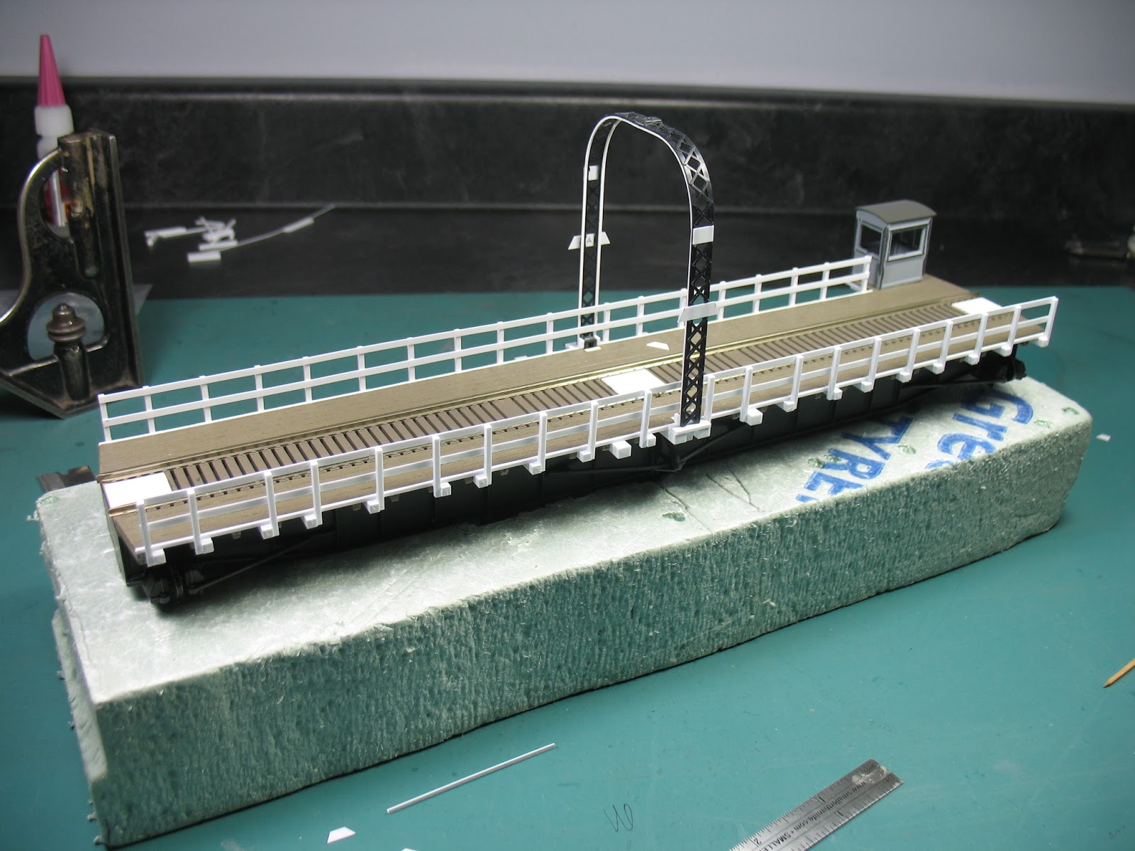
The offending parts have been removed in the photo below. A piece of thick foam with a hole cut into the center the same size as the one in the turntable pit made a good work surface to kitbash the bridge.

The bridge deck has nice wood grain planking very similar to the prototype. The small platform cantilevered off the side in the center off the deck seen below is not on the prototype and will be cut off flush with deck.


The photo below shows styrene cross timbers below the deck have been added, spacing dimensions were taken from a drawing in the Bob Rzasa turntable article.


In this next photo hand railing matching the prototype is being added again using dimensional data from the Bob Rzasa article. Additional deck planking sections have been added between the rails as per prototype.


The power arch is the next piece to add. The prototype arch girder has a diagonal lattice pattern on the outside. To model this an easy route was taken, Central Valley bridge girders were used. The photo below shows that the lattice faces of two bridge girders has been separated from the solid web portion of the girders. Again using the dimensional data from the Bob Rzasa article the correct radius curves were bent into the pieces, then the pieces were trimmed to the needed height and width dimensions. The Central Valley plastic is very malleable and will hold a shape after bending, in this case a specific radius.


In order to assemble the two halves of the arch together a quick jig was fashioned. Working on a flat glass surface a straight edge was held down with some masking tape and five styrene blocks were temporarily glued the the glass outlining the height and width of the arch.  


Below using the jig to align then glue the two halves of the lattice arch together. After the lattice arch was glued and now one piece, strips of .010" x .030" styrene were glued to both inside edges of the arch, this was done in two layers staggering the joints. The styrene strips significantly reinforce and hold the desired shape of the arch.


Here the arch has been attached to the bridge.


The prototype operators enclosure is pictured below. Flat sheet metal forms the exterior surfaces. There is no door but the door opening has an unusual radius corner at the top left and a square corner on the other side. A control lever can be seen inside. Sure wish I took more photos of this 40 years ago!


The operators enclosure that was included with the turntable is reused, but the molded on detail of the four sides was filed flat so the enclosure can be re-sided with new styrene sides simulating the flat sheet metal sides of the prototype. Below the four new sides are shown before gluing to them to the enclosure.


Because the enclosure has no door, a lever and some controls can be seen on the inside of the prototype. Some basic control details seen above were added to the inside of the enclosure before the sides and roof were glued on.

The thru the floor control lever below was made from some brass bar stock and rod. This was attached to the enclosure floor before the enclosure was reattached to the bridge deck.


The finished "Danbury-ized" turntable bridge now painted all black as the prototype was in the 1950's.


Couple of photos after some weeds have been added to the scene.


It is doubtful that a prototype Alco DL-109 was ever turned at Danbury, but what the heck!


Not a perfectly accurate model but it will do the job. Maybe some more weathering in the future. The Walthers turntable operates very smoothly, a great addition to the layout.