Monday, October 20, 2025

Modeling State Line Interchange Yard & Rising Junction part 12 - Structures

Painting and assembly

Interior colors

The interior colors of the State Line roundhouse are not documented and available black and white photos offer no proof. 

Several photos of New Haven roundhouses show a two color scheme of a dark color on the lower portions of the walls where dirt would most likley collect and a lighter color for everything above affording reflected light.

An interior photo of the then new Danbury CT roundhouse below is an example this two color scheme.

A dark gray on the lower portions and a lighter gray on the upper portions of the interior seemed to be a good guess for the roundhouse model.

Assembly begins by gluing the two color machineshop walls to the roundhouse floor below.

Exterior color

In a rare color photo of the prototype below, the entire exterior of the structure appears to be a monochrome light tan/brown color used on many New Haven structures, this scheme will be used on the model.

A different view of the model shows the chosen light tan/brown color applied to the exterior front wall of the machineshop.

The prototype roundhouse floor is 5" thick concrete covered with 3/4" of asphalt. An asphalt color was weathered and applied to the floor before assembly of the walls and roof supports.

Two exterior walls over the door openings are assembled with the painted roof supports between the engine bays.

The remaining engine bay wall, side wall and rear walls complete the sides of the roundhouse.

Next roof is next.

Wednesday, September 10, 2025

Wordless Wednesday (almost)

Jim Dufour stopped by for a visit today. The hours flew by while we had great fun running freight train RI-2 between Danbury CT and the interchange yard with the B&A at Stateline MA.

Jim says I need to start posting on this blog again, he is right, will do Jim! 

More to come.


Tuesday, May 6, 2025

Modeling State Line Interchange Yard & Rising Junction part 11 - Structures

Roundhouse roof supports

The blank left exterior wall will not be seen once the structure is in place on the layout. The interior side of the same wall will be inclosed as part of the shop/boiler room and also not be seen on the completed model, this makes a good surface plate for a jig to assemble the floor to roof supports.

The styrene blocks glued to the interior wall below will locate the prototypical 10"x10" vertical support posts while gluing the roof joists in place completing the assembly. 

It is worth mentioning that the set of plans acquired from UCONN have a separate roof support plan that would allow a model to be built exactly complex as the prototype. This would not be seen on the completed model, so the much simplified support below will be adequate. 


The vertical supports have a hole drilled into the center of to bottom of each post to glue in a .025" diameter locating pin, see below.


These pins will exactly locate the roof supports to the floor when inserted into the base plates glued on the floor in part 9 as below.  The posts are now free standing but removable for painting before final assembly.


Painting the all the structure components to this point and assembly will be next.

Thursday, April 10, 2025

Modeling State Line Interchange Yard & Rising Junction part 10 - Structures

Roundhouse sides, ends & windows

The original NH roundhouse plans purchased from the UCONN library has a good elevation drawing of one side of the roundhouse. 

This drawing offeres little in working dimensions but the 106' 11" length of the structure sides plus window and door dimensions and their locations are known from the base floor plan. Enlarging this drawing to HO scale will later be a guide in locating and sizing the roof top ventilators.

When the finished roundhouse model is installed on the layout, the side that will be seen from the aisle is the opposite side from this drawing. Following standard practice for structures on the layout, the unseen side below will remain a blank styrene sheet.  

Windows

Window and door dimensions are unique to this roundhouse and not available in HO scale.

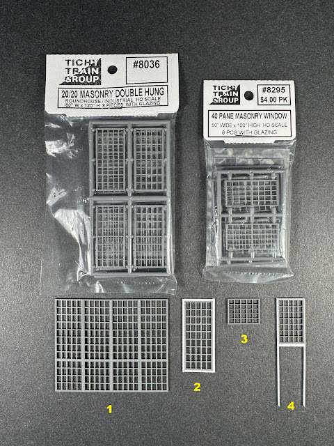
Ready made windows from Tichy Train Group that can be kitbashed to resemble the prototype are used as a starting point, the finished product will be close enough to suite the needs of this layout.

The photo below shows the two types of Tichy windows used and the finished windows kitbashed from them.

Windows #1 are the large windows that will be located in the back ends of the roundhouse, these are made from Tichy #8036.

Windows #2 are the side windows and frame, also made from #8036.

Windows #3 will be located above the front roundhouse door openings and boiler room, made from Tichy #8295.

Windows #4 above the side doors are also from #8295, shown here with the door frame. The associated sliding side doors have an unusual width and height and will be scratchbuilt, #8036 will also be used for the door windows (not shown).

The sides and ends

The above drawing indicates that novelty or clapboard siding was to be used on this structure. In the photo below although not very clear, it appears that the siding may be the novelty type and will be used on the model.

Evergreen styrene .040" novelity siding was purchased in a longer 12" x 24" sheet so the length of the sides could be made in one continuous piece. With the window sizes established the openings are cut out.

The front of the roundhouse will also be seen once in place on the layout. The boiler room/shop wall and plain surfaced walls over the engine bays are made and windows test fitted in photo below.

The side finished with windows installed, scratchbuilt doors and all trim in place below.

The rear walls of the engine bays will be seen from the inside only as in the prototype photo above. Below, the three assenbled inside walls.

Next, the engine bay roof supports will be assembled.


Wednesday, March 12, 2025

Modeling State Line Interchange Yard & Rising Junction part 9 - Structures

Roundhouse floor

The roundhouse baseplate made with masonite in part 8  has been covered with .040" styrene, the roundhouse floor surface now being the same material that building will be modeled with making it easier to glue all of the individual structure pieces to the floor with a styrene cement. The styrene was glued to the Masonite with ACC.

The styrene floor was not made one piece, there are four larger full length pieces, one of each located on ether side of the inspection pits with a smaller filler piece at the back end of each pit at the rear of the roundhouse. 

A styrene jig cut to the full pit length of and width between the rails was made to hold the rails in gauge when gluing the rails to the masonite baseplate on ether side of the inspection pits. Once the rails were in place the jig was cut into three pieces to be used as filler pieces at the front of the inspection pits at the roundhouse entrance.

The rails are cut .375" longer that the inspection pits, this leaves an open slot for the rails of the lead tracks from the turntable to slip into so the rail joints are inside the building and not at the hard transition between the roundhouse floor and the outside ground.

Before the rails were glued inplace a power feed wire was soldered to the rear end of each rail, the wires are taped between the rails to keep them out of the way until the structure is finally located into the layout.

Baseplates for the roof support posts were glued in place at this step, they may be hard to see in the below photo. Each plate has a .030" hole drilled into the center of the plate, these holes will later accept a corresponding pin affixed in the center of each support post to locate them during assembly. 

Next step will be to make the roundhouse sides and ends.

Wednesday, February 19, 2025

Modeling State Line Interchange Yard & Rising Junction part 8 - Structures

Several signature structures are needed to complete the State Line interchange yard and Rising Junction dioramas. Modeling efforts for the layout will now focus on these structures until completed.

As a reference, part 3 of this series describes layout location of the roundhouse and associated turntable. Parts 4 & 5 are about the modeling of the now completed turntable. 

Modeling the 1918 roundhouse

The foundation 

Fortunately for modeling, there are a set of original New Haven Railroad State Line roundhouse plans available for purchase from the University of Connecticut Library archives at the Storrs CT. campus.

Printing the ground floor plan from the set in HO scale has been very helpful in transferring the dimensions of the foundation in relation to the turntable and locating the structure onto the layout surface, see below.

After marking the four corners of the structure onto the layout surface, the print was trimmed to just the foundation footprint. 

Next, the inspection pits were cut out of the print and the locations were transfered to the layout surface and cut in.


A piece of 1/8" masonite will be used as the base plate to build the model on.

The same print is used to mark and cut out the masonite.


The original plans indicate that the roundhouse floor was concrete covered with asphalt.

Next, to model the floor surfce the masonite will be covered with .040" styrene.